
Videos
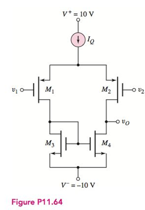
The differential amplifier in Figure P11.64 has a pair of PMOS transistors as input devices and a pair of NMOS transistors connected as an active load. The circuit is biased with
Want to see the full answer?
Check out a sample textbook solution
Chapter 11 Solutions
Microelectronics: Circuit Analysis and Design


- From the figure shown, when S1 is at 1 : up position; the following statement is not correct except: (a) Collector-emitter voltage of Q1 is approximately zero (b) the LED will illuminate (c) the base voltage of Q2 is equal to 9 V (d) (b) and (c)arrow_forwardcircuits by using the small signal models of the transistor. Assume the Early voltage of the transistors are infinitely large. Calculate the small-signal input and output impedances of the following Vcc R1 R1 Rout VB RE Rin R2arrow_forward(ii) Calculate the RB, Rc, and the minimum power rating of the transistor (Note: the actual power rating should be greater).arrow_forward
- 4. For the transistor in the figure shown below, the parameters are ß = 100 and VÀ = ∞. a. Design the circuit such that lEQ = 1mA and the Q-pt is in the center of the dc load line. b. If the peak-to-peak sinusoidal output voltage is 4V, determine the peak-to-peak sinusoidal signals at the base of the transistor and the peak-to-peak value of Vs. If the load resistor R₁ = 1kQ is connected to the output through a coupling capacitor, determine the peak-to-peak value in the output voltage, assuming vs is equal to the value determined in part (b). Vcc=+10 V www Rs = 0.7 kΩ Cc www RB RE voarrow_forward6. This problem involves designing a differential amplifier of the following figure. You may assume that the body and source terminal is shorted and you can neglect channel length modulation. Use the following MOSFET parameters: Parameter N-channel P-channel Units +1.10 -1.20 V 5. 2E-5 A/v 1.5E-5 a) Choose IBIAS for an output DC bias level Vo1(Dc) = Voz(DC)=3.00 V. b) Determine the voltage gain of the differential amplifier. c) Determine the magnitude of the small signal common mode gain. VDD = +5V RD1 5kQ RD2 5kO Voi0 o Vo2 M1 M2 W/L=80/2 w/L=80/2 ) IBIAS Vss = -5Varrow_forwardTransistors originally were made with germanium but modern transistors use silicon for its higher heat tolerance. Transistors amplify and switch signals. They can be analog or digital. Two prevalent transistors today are Metal-Oxide-Semiconductor Field Effect Transistors (MOSFET) and Bipolar Junction Transistors (BJT).In your own understanding in the field of electronics can you compare and contrast which one has merit over the other ?arrow_forward
- Given a D-MOSFET circuit used as an amplifier with the following parameter: IDSS=12mA and a transconductance of gm=3.2 mS. Determine the DC drain to source voltage VDS and the AC output voltage if Vin=500 mV.arrow_forward. Design a fixed bias-transistor circuit using V = Vcc = 10 V for a Q-point of Iç = 5 mA and Va 4 V. Assume Boc = 100.The design involves finding R, and Rc. inakomeont thot one is hiasedarrow_forwardModel parameters are as under: (LEVEL=2 VTo=1.4 Kp=.6m LAMBDA=0.005 Cbd=100f Cbs=100f)arrow_forward
- application of bias circuits of the BJT in AC a. determine Zi and Zo b. Calculate Av and Ai c. repeat literal (a) with ro = 20k ohm d. repeat literal (b) with ro = 20k ohmarrow_forwardTime left 1:46:17 A bipolar junction transistor is described in the figure below. The transistor is implemented in the circuit with Vcc, Rc, and RB equal to 16 volts, 2k, and 10kn. Determine the value of Vout if Vin = 1.1V. V... in RB B Vec Ro V E outarrow_forward1. For the circuit in Figure 1: a) Calculate the input and output power if the input signal results in a base current of 5 mA rms. b) Calculate the input power dissipated by the circuit if Rg is changed to 1.5 kN. c) What maximum output power can be delivered by the circuit if RB is changed to 1.5 kN? d) If the circuit is biased at its center voltage and center collector operating point, what is the input power for a maximum output power of 1.5 W? +Vcc (18 V) Rc = 16 2 RB 1.2 k2 V. B - 40 100 µF Figure 1arrow_forward
 Introductory Circuit Analysis (13th Edition)Electrical EngineeringISBN:9780133923605Author:Robert L. BoylestadPublisher:PEARSON
 Delmar's Standard Textbook Of ElectricityElectrical EngineeringISBN:9781337900348Author:Stephen L. HermanPublisher:Cengage Learning
 Programmable Logic ControllersElectrical EngineeringISBN:9780073373843Author:Frank D. PetruzellaPublisher:McGraw-Hill Education
 Fundamentals of Electric CircuitsElectrical EngineeringISBN:9780078028229Author:Charles K Alexander, Matthew SadikuPublisher:McGraw-Hill Education
 Electric Circuits. (11th Edition)Electrical EngineeringISBN:9780134746968Author:James W. Nilsson, Susan RiedelPublisher:PEARSON
 Engineering ElectromagneticsElectrical EngineeringISBN:9780078028151Author:Hayt, William H. (william Hart), Jr, BUCK, John A.Publisher:Mcgraw-hill Education,