
Concept explainers
Videos
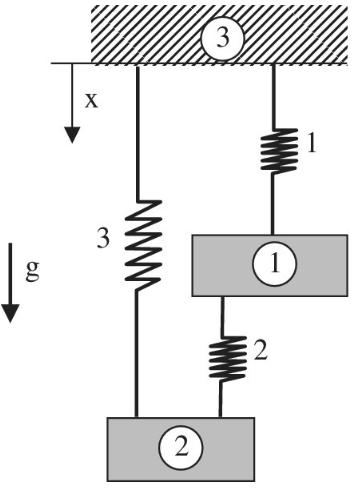
Two rigid masses, 1 and 2, are connected by three springs as shown in the figure. When gravity is applied with
Want to see the full answer?
Check out a sample textbook solution
Chapter 1 Solutions
Introduction To Finite Element Analysis And Design
Additional Engineering Textbook Solutions
Mechanics of Materials (10th Edition)
Engineering Mechanics: Statics & Dynamics (14th Edition)
Heating Ventilating and Air Conditioning: Analysis and Design
Manufacturing Engineering & Technology
DeGarmo's Materials and Processes in Manufacturing
Engineering Mechanics: Dynamics (14th Edition)


- A uniform bar AB of weight W = 25 N is supported by two springs, as shown in the figure. The spring on the left has a stiffness k[= 300 N/m and natural length Lt=250 mm. The corresponding quantities for the spring on the right are k2= 400 N/m and L^ = 200 mm. The distance between the springs is L = 350 mm, and the spring on the right is suspended from a support that is a distance it = SO mm below the point of support for the spring on the left. Neglect the weight of the springs. (a) At what distance x from the left-hand spring (figure part a) should a load P = 18 N be placed in order to bring the bar to a horizontal position? (b) If P is now removed, what new value of k{is required so that the bar (figure part a) will hang in a horizontal position underweight If? (c) If P is removed and kt= 300 N/m. what distance b should spring ktbe moved to the right so that the bar (figure part a) will hang in a horizontal position under weight II"? (d) If the spring on the left is now replaced by two springs in series (kt= 300 N/m, kt) with overall natural length Lt= 250 mm (see figure part b). what value of k; is required so that the bar will hang in a horizontal position under weight IF?arrow_forwardA stepped shaft ABC consisting of two solid, circular segments is subjected to uniformly distributed torque t1acting aver segment 1 and concentrated torque t2applied at C, as shown in the figure. Segment 1 of the shaft has a diameter of d1= 57 mm and length of L1= 0.75 m; segment 2 has a diameter d2— 44 mm and length L2= 0.5 m. Torque intensity /,"= 3100 N . m/m and T2= 1100 N. m. (a) Find reaction torque TAat support A. (b) Find the internal torque T(x) at two locations: .x = L1/2 and at .x = L1+ L2/2. Show these internal torques on properly drawn free-body diagrams.arrow_forwardSolve the preceding problem if the collar has mass M = 80 kg, the height h = 0.5 m, the length L = 3.0 m, the cross-sectional area A = 350mm2. and the modulus of elasticity E = 170 GPa.arrow_forward
- Solve the preceding problem for the following data: b = 6 in., b = 10 in, L = 110 ft, tan a = 1/3, and q = 325 lb/ft.arrow_forwardA round bar ABC of length 2L (see figure) rotates about an axis through the midpoint C with constant angular speed w (radians per second). The material of the bar has weight density y. (a) Derive a formula for the tensile stress a’ in the bar as a function of the distance x from the midpoint C. (b) What is the maximum tensile stress a max?arrow_forwardTwo rigid bars are connected to each other by two linearly elastic springs. Before loads are applied, the lengths or the springs are such, that the bars are parallel and the springs are without stress. (a) Derive a formula for the displacement E4at point 4 when the load P is applied at joint 3 and moment PL is applied at joint 1. as shown in the figure part a. (Assume that the bars rotate through very small angles under the action of load P.) (b) Repeat part (a) if a rotational spring, kr= kL2, is now added at joint 6. What is the ratio of the deflection d4 in the figure part a to that in the figure part b ?arrow_forward
- A polyethylene tube (length L) has a cap that when installed compresses a spring (with under-formed length L1) by an amount ?? = (L1 = L). Ignore deformations of the cap and base. Use the force at the base of the spring as the redundant. Use numerical properties given in the boxes. (a) What is the resulting Force-in the spring, Fk? (b) What is the resulting Force in the tube, Ftl (c) What is the filial length of the tube, Lf? (d) What temperature change ?T inside the tube will result in zero force in the springarrow_forwardTruck suspensions often have "helper springs" that engage at high loads. One such arrangement is a leaf spring with a helper coil spring mounted on the axle, as shown in the figure below. When the main leaf spring is compressed by distance yo, the helper spring engages and then helps to support any additional load. Suppose the leaf spring constant is 5.15 x 10⁵ N/m, the helper spring constant is 3.80 x 10⁵ N/m, and y₁ = 0.500 m. m Need Help? Truck body Main leaf spring (a) What is the compression of the leaf spring for a load of 4.90 x 10⁵ N? Read It -"Helper" spring Axle (b) How much work is done in compressing the springs?arrow_forwardTwo massless springs with different spring constants k₁= 100 N/m and k₂ = 10 N/m are aligned vertically, as shown in figure 1. A block of mass m = 0.12 kg is placed on the bottom spring. The distance between the top of the box and the top spring is h = 0.35 m. You compress the bottom spring Ay = 0.3 m from its equilibrium position (figure 2). When you let go, the box flies up (figure 3) and compresses the top spring (figure 4). Treat the upward direction (↑) as positive, such that the compression of the top spring is a positive displacement. What is the maximum compression of the top spring due to the flying box? Give your answer in units of meters to 2 decimal places. Use g = 9.8 m/s^2. Assume air resistance is negligible. T h EW Ay (2) www Backup link to image (opens in new tab). fumand M риту 4 ² ↑ M ? wwwarrow_forward
- A 0.20 kg horizontal beam has length L=0.8 m. It is supported by a fulcrum at d=0.55 m from the left end. A 0.15 kg mass ml is suspended at xl=0.15 m from the bar's left end. Another mass mr is suspended at xr=0.65 m from the bar's left end. The system is in equilibrium. How heavy in kg is the mass mr on the right side? Hint: the bar's gravity has a torque if it is not supported by the fulcrum at exactly half way.arrow_forwardThe first figure gives spring force Fx versus position x for the spring-block arrangement of the second figure. The scale is set by Fs = 190 N. We release the block at x = 13.0 cm. How much work does the spring do on the block when the block moves from x; = +9.0 cm to (a) x = +5.0 cm, (b) x = -5.0 cm, (c) x = -9.0 cm, and (d) x = -11.0 cm? -x (cm) -2 -1 -F, X* = 0 Block attached to spring F = 0 (a) x positive F, negative F (b) x negative F, positive (c)arrow_forward3. 2 ft 1106 2 ft B ww Cord AB is 2 ft long, the force P = 76 lb, the angle 0 = 56 degrees and the spring's stiffness is k = 56 Ib/ft.arrow_forward
 Mechanics of Materials (MindTap Course List)Mechanical EngineeringISBN:9781337093347Author:Barry J. Goodno, James M. GerePublisher:Cengage Learning