
Concept explainers
Videos
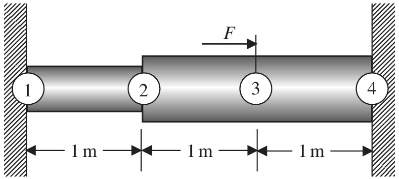
A stepped bar is clamped at both ends. A force of
a. Sketch the displacement field
b. Calculate the stress at a distance of 2.5 m from the left support.
Want to see the full answer?
Check out a sample textbook solution
Chapter 1 Solutions
Introduction To Finite Element Analysis And Design
Additional Engineering Textbook Solutions
Thinking Like an Engineer: An Active Learning Approach (3rd Edition)
Applied Fluid Mechanics (7th Edition)
Heating Ventilating and Air Conditioning: Analysis and Design
Manufacturing Engineering & Technology
Statics and Mechanics of Materials (5th Edition)
Fundamentals Of Thermodynamics


- The 10 kN load is applied at the free end of the bar as shown in Figure Q4. Let modulus of elasticity E = 200 GPa, the shear modulus G= 80 GPa, and the Poisson's ratio v=0.3. The diameter of the bar is 40 mm. a) Determine the displacement in -y direction of end D by using Castigliano's second theorem. b) Determine the rotation about x' axis of end D by using Castigliano's second theorem. c) Without any calculation, explain whether the rotation about x' axis of end D increases if the applied load is increased from 10 kN to 20 kN. Consider the strain energy due to axial, bending and torsion only. Neglect the strain energy due to transverse shear. B D 10 kN 200 mm 150 mm- 150 mmarrow_forwardA long circular shaft of length L with variable cross-section is fixed onto rigid walls as shown in Figure 1.1. The polar moment of inertia of the L/3-long segment (J1) with a larger cross section is three times larger than that of a 2L/3-long segment (J2) on the right. Assume the shear modulus is constant and equal to G for the entire shaft and that strains are small and linear elastic. L/3 L/3 L/3 Figure 1.1. Shaft with variable cross-section and external torque T. (a) If the shaft is subjected to an external torque T at point b, find the angle of twist of point b with respect to point a. (b) If the shaft is subjected to an external torque T at point a, as shown in Figure 1.2, find the angle of twist of point a with respect to point b. L/3- L/3 b J2 L/3 Figure 1.2. Shaft with variable cross-section and external torque T.arrow_forwardAnalyse the statically determinate bar illustrated below by expressing the loading as a single function using Macaulay brackets and the Dirac delta, integrating to find th axial force and integrating again to find the displacements, applying the boundary conditions appropriately. Find the axial force in the bar at point A and the displaceme at point B. The cross section of the bar is constant with EA = 18000 kN. a = 4 m, b = 2 m, c = 2 m and d = 4 m. w1 = 12 kN/m, w2 = 17 kN/m,, P1 = 12 kN and P2 = 19kN. a W1 L/2 W2 Multiple Choice Answers Multiple Choice Answer: Axial force at point A (kN, tension positive): a. 3.31 b. 31.97 c. 37.33 d. 31 Multiple Choice Answer: Displacement at point B (mm, positive to right): a. 0.0061 b. 0.0395 c. 0.0193 d. 0.0261 Axial force at point A (kN, tension positive): Displacement at point B (mm, positive to right): L/2 P1 P2 (type in your multiple choice answer, e.g. a, b, c or d) (type in your multiple choice answer, e.g. a, b, c or d)arrow_forward
- Two blocks are connected by an ideal string, which passes over a pulley without slipping (see figure). The magnitudes of the wire voltages applied to blocks 1 and 2 are represented, respectively, by T1 and T2. Consider T2>T1. In this case, the pulley rotates counterclockwise. The pulley has radius R=0.10 m and rotates around an axis perpendicular to its surface passing through its CM. The CM of the pulley coincides with its center. The pulley's moment of inertia about the axis of rotation is denoted by I and its angular acceleration is α=0.50 rad/s2. If T2=87 N and T1=50 N, determine I (in kg⋅m2). A) 0,67 B) 0,56 C) 15 D) 28 E) 24 F) 0,85 G) 14 H) 7,4arrow_forwardF = F cos # F = F + F F F sin 8. # tan Exampie (1):Find the two components of the force (100 X) if: 0 = 30", 120 270° as shown in figure. F = 100 N F = 100 N 6=30 0 =120° 0 =270 0 = 30 0 =60 F = 100 N lution:arrow_forward3. 2 ft 1106 2 ft B ww Cord AB is 2 ft long, the force P = 76 lb, the angle 0 = 56 degrees and the spring's stiffness is k = 56 Ib/ft.arrow_forward
- Write down the governing equation and derive the boundary conditions in terms of displacement field for the beam in the following figure. P.arrow_forwardThe bar in the figure of length L has Young's modulus E and cross-sectional area A. Said bar is subjected to an axially distributed load of intensity p(x) units of force per unit of length. It is requested to determine the displacement field u(x) of the bar.arrow_forwardConsider the following spring system. 直一 m, 2 with spring constants c = 5 Assume down is the positive direction. Write the elongation matrix A = Write the stiffness matrix K =arrow_forward
- h B h + d + d d THE FIGURE IS NOT DRAWN TO SCALE. Also, A and E are BOTH pinned (hinged) supports (even though they're not drawn that way). Numerical values for the parameters shown are P = 680 N, d = 0.40 m and h = 0.40 m. For component directions, use x positive to the right and y positive upward.arrow_forwardIn the graph the force versus displacement of a spring is given (the spring is shown in a separate figure--see below). The x-axis range is ±2 cm. The y-axis range is tFs, where Fs = 220 N. How much work does the spring do on the block (the mass "m") when the block moves from x₁ = 7.6 cm to 4.3 cm? W J y F. X -1.5 -0.5 0 10.5 1 1.5 -F How much work does the spring do on the block (the mass "m") when the block moves from x; = 7.6 cm to -7.6 cm? W = Question Help: Read Submit Question marrow_forward8:30 Test 3.pdf F1 F2 a CF3 A b a F4 D Consider the following values: - F5 a = 12 m; b = 10 m; c = 10 m; d = 8 m; F1 = 6 kN; F2 = 7 kN; F3 = 8 kN; F4 = 9 kN; F5 = 10 kN; a = 30°, 0= 45° , B = 60° 1] What is the resultant moment of the five forces acting on the rod about point A? a) - 111.6 kN.m b) 112.6 kN.m e) - 184.6 kN.m d) - 109.6 kN.m e) - 104.1 kN.m 0 None of them 21 What is the resultant moment of the five forces acting on the rod about point B? a) -95.8 KN.m b) 42.7 kN.m c) 80.9 kN.m d) 10.9 kN.m e) 51.8 kN.m ) None of them 31 What is the resultant moment of the five forces acting on the rod about point C? b) - 21.1 kN.m e) 17.4 kN.m d) - 16.5 kN.m e) 15.6 kN.m ) None of them a) 32.6 kN.m 4] What is the resultant moment of the five forces acting on the rod about point D? a) 37.6 kN.m b) 73.8 kN.m c) 71.6 kN.m d) 52.1 kN.m e) 21.1 kN.m ) None of them 5] What is the moment of the force F2 about point E? a) 90.7 kN.m b) - 88.1 kN.m c) 54.6 kN.m d) 103.1 kN.m e) 100.7 kN.m ) None…arrow_forward
 Elements Of ElectromagneticsMechanical EngineeringISBN:9780190698614Author:Sadiku, Matthew N. O.Publisher:Oxford University Press
 Mechanics of Materials (10th Edition)Mechanical EngineeringISBN:9780134319650Author:Russell C. HibbelerPublisher:PEARSON
 Thermodynamics: An Engineering ApproachMechanical EngineeringISBN:9781259822674Author:Yunus A. Cengel Dr., Michael A. BolesPublisher:McGraw-Hill Education
 Control Systems EngineeringMechanical EngineeringISBN:9781118170519Author:Norman S. NisePublisher:WILEY
 Mechanics of Materials (MindTap Course List)Mechanical EngineeringISBN:9781337093347Author:Barry J. Goodno, James M. GerePublisher:Cengage Learning
 Engineering Mechanics: StaticsMechanical EngineeringISBN:9781118807330Author:James L. Meriam, L. G. Kraige, J. N. BoltonPublisher:WILEY