
Concept explainers
Videos
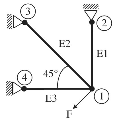
The truss structure shown in the figure supports the force F. The finite element method is used to analyze this structure using three truss elements as shown. The area of cross- section (for all elements)
a. Determine the stiffness matrix of element 2.
b. It is determined after solving the final equations that the displacement components of node 1 are:
c. What is the change in length of element 2?
Want to see the full answer?
Check out a sample textbook solution
Chapter 1 Solutions
Introduction To Finite Element Analysis And Design
Additional Engineering Textbook Solutions
Introduction to Heat Transfer
Thinking Like an Engineer: An Active Learning Approach (3rd Edition)
Statics and Mechanics of Materials (5th Edition)
Heating Ventilating and Air Conditioning: Analysis and Design
Mechanics of Materials
Fundamentals Of Thermodynamics


- Dont Copy from chegg need step wise step and correct answers only Use Finite Elemental method Assemble element stiffness matrix for the member of plane frame shown in Figure is oriented at angle 30° to the x-axis. Take E= 200 GPa, I=4 × 10⁶ m* and A = 4 × 10-³m². ,if it 5m 30arrow_forward1. For the plane truss supported by the spring at node 1, determine the nodal displacements and the axial forces in each element. Use the direct stiffness (displacements) method. Use E = 210 GPA, A = 0.0002 M². Use direct stiffness method in the most efficient way (symmetry), state your simplifications. ( W 2 100 KN Sm 60⁰ 5 m 60⁰ 3 k=6000 kN/marrow_forwardA mechanism carries a constant load P applied to the seat as shown. E For the angle 8, determine the following: (a) the lengths LBE and LAB, in m (b) the angles a and $, in degrees Draw the complete FBD of (c)members AB, FG, EBH and GHI 100 175 Parameter (A= 1 B=3 C= 6 D= 2 E=0) P = 762 N 0 = 32° Note: Figures CDFE and EFGH are parallelograms. 400 800 200 LBE C cont D 150 400 175 900 150 200 Dimensions in millimeters H 150arrow_forward
- 1. A steel bar with the dimensions and cross section shown is suspended vertically. Three concentric downward loads are applied to the bar: 22 250N at the lower end; 13 500N at 0.35m above the lower end, and 9000N at 1m above the lower end. The modulus of elasticity of the steel is 210GPa. What is the total change in length of the bararrow_forwardExample The beam ABC is loaded via a 500 N.m couple and a 600 N force as shown. The beam is connected to the rest of the system by a pin joint at B and a roller support at C. Determine the magnitude of the reaction forces on the beam at the supports. 600 N 500N.m 400 300 500 Ans. RC=1700 N RBx=1597.5 N Dimensions in mm 20 RBy=1181.4 Narrow_forwardA rectangular steel block is 3 inches long in the x direction, 2 inches long in the y direction, and 4 inches long in the z direction. The block is subjected to a triaxial loding if three uniformly distributed forces as follows: 48 kips tension in the x direction, 60 kips compression in the y direction, and 54 kips tension in z direction. If v=0.30 and E=29x10^6 psi, determine the single uniformly distributed load in the x direction that would produce the same deformation in the y direction as the original loading. DetermineNormal strain in x, y & z direction.Elongation in x, y & z direction.arrow_forward
- A rectangular steel block is 4inches long in the x direction, 2inches long in the y direction, and 3inches long in the z direction. The block is subjected to triaxial loading of three uniformly distributed forces as follows: 50kips tension in the x direction, 65kips compression in the y direction, and 55kips tension in the z direction. If v=0.30 and E=29x10^6 psi. a. What is the total elongation in the x-direction? b. What is the total elongation in the y-direction? c. What is the total elongation in the z-direction? d. Single Uniformly Distributed Load in the x-direction that would produce the same deformation in the z-direction as the original loading -Draw and label the diagram correctly, No diagram in the solution will be marked wrong. -Shortcut solution will be marked wrong.- Direction of the assumption of the equilibrium equation must be shown, no direction will be marked wrong.arrow_forwardA truss, formed of two members, is subjected to a horizontal force P=2,600 lb applied at node 1 (as shown below). Suppose that the cross- sectional area and Young's modulus of both members are A=2.0 in² and E=40x106 psi, respectively. Determine the horizontal displacement of node 1 (in inch). Hint: round off your final answer to 5 decimal places; e.g. if your answer is 1.2345678, then rounding-off to 5 decimal places yields 1.23457 and thatarrow_forwardConsider a rigid rod that is subjected to two external forces and is fixed to the wall at A. The following figure displays the rod's free body diagram. Answer the following questions using the provided FBD. 2.5 -1 1 3.5 The support reaction at A along x-axis (A) is The support reaction at A along y-axis (Ay) is The support reaction at A along z-axis (A.) is The Moment reaction at support A about x-axis (Ma) is -1 n 1 0 -2.5 2.5 -1 -3.5 5.5 -5.5 -0.5 0.5 A₂ Mx4 Z M₂ My KN KN KN 3m KN.m 1m 1 KN 2m 2.5 KNarrow_forward
- The following figure represents a 3-nodes, two-element truss structure with identical cross-sectional area A = 100 mm2 and modulus E = 200 GPa for each element. It is supported by a pin at global node 1, an inclined roller at 135˚ at global node 2 and a horizontal roller at global node 3. A force P = 400 kN is applied at global node 2. Using the direct approach and the minimum number of linear finite elements, what would be the displacement at the global node 2 of the inclined roller in its local coordinate system? Select one: û2 = 2.83 mm û2 = 8.32 mm û2 = 3.83 mm û2 = - 6.32 mmarrow_forwardThe cantilever truss in the figure is hinged at D and E. Find the force in member AB. 1000 1b 60% 60 30 C 10' lo00 16 000 16.arrow_forwardExample The beam ABC is loaded via a 500 N.m couple and a 600 N force as shown. The beam is connected to the rest of the system by a pin joint at B and a roller support at C. Determine the magnitude of the reaction forces on the beam at the supports. 600 N 500N.m 400 300 500 Ans. RC=1700 N RBx=1597.5 N Dimensions in mm REDMI NOTE 9 PRO AI QUAD CAMERA RBy=1181.4 Narrow_forward
 Elements Of ElectromagneticsMechanical EngineeringISBN:9780190698614Author:Sadiku, Matthew N. O.Publisher:Oxford University Press
 Mechanics of Materials (10th Edition)Mechanical EngineeringISBN:9780134319650Author:Russell C. HibbelerPublisher:PEARSON
 Thermodynamics: An Engineering ApproachMechanical EngineeringISBN:9781259822674Author:Yunus A. Cengel Dr., Michael A. BolesPublisher:McGraw-Hill Education
 Control Systems EngineeringMechanical EngineeringISBN:9781118170519Author:Norman S. NisePublisher:WILEY
 Mechanics of Materials (MindTap Course List)Mechanical EngineeringISBN:9781337093347Author:Barry J. Goodno, James M. GerePublisher:Cengage Learning
 Engineering Mechanics: StaticsMechanical EngineeringISBN:9781118807330Author:James L. Meriam, L. G. Kraige, J. N. BoltonPublisher:WILEY