
Videos
A stepped bar is clamped at one end and subjected to concentrated forces as shown.
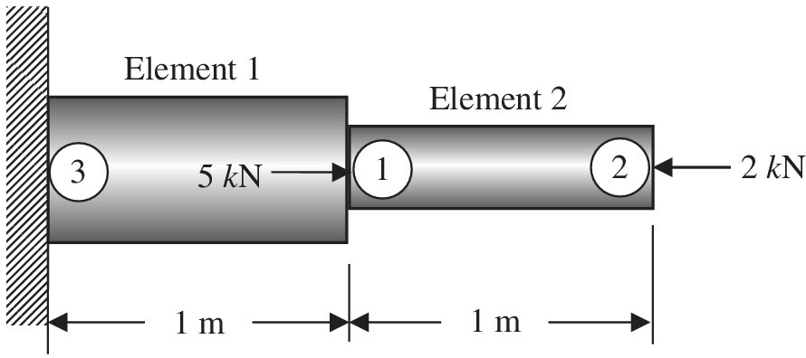
Assume:
a. Write the element stiffness matrices of elements 1 and 2 showing the row addresses.
b. Assemble the above element stiffness matrices to obtain the following structural level equations in the form
c. Delete the rows and columns corresponding to zero DOFs to obtain the global equations in the form of
d. Determine the displacements and element forces.
Want to see the full answer?
Check out a sample textbook solution
Chapter 1 Solutions
Introduction To Finite Element Analysis And Design
Additional Engineering Textbook Solutions
Fox and McDonald's Introduction to Fluid Mechanics
Applied Statics and Strength of Materials (6th Edition)
Engineering Mechanics: Statics
Mechanics of Materials (10th Edition)
Automotive Technology: Principles, Diagnosis, and Service (5th Edition)
Fundamentals Of Thermodynamics


- II. A circular column is made of concrete [E. 4.2(10³)ksi] while being reinforced with six steel rods [Est = 29 (10³)ksi]. It is acted upon 4 in. - 30 kip by an axial force of 30 kip as shown in the figure to the right. Each rod has a diameter of 0.85 in. 3 ft Solve for the following: a) Force in each steel rod, Pst b) Force in the concrete, P. c) Stress in each steel rod, Ost = kip kip %3D ksi d) Stress in the concrete, oc = ksiarrow_forwardWhat is the size of the stiffness matrix of a 4-node quadrilateral element?arrow_forwardClassify structure shown in Figure as statically determinate, statically indeterminate, or unstable. If indeterminate, specify the degree of indeterminacy. h A B (1) 0₁ b (2) C W 2 021 b O a. Statically indeterminate to the Third degree O b. Statically indeterminate to the first degree O c. Statically indeterminate to the Second degree O d. Statically indeterminate to the Fourth degree O e. Statically determinate. D W 2arrow_forward
- Handwrite and step by step solutions The figure shows a cross section of a conventional loudspeaker. A voice coil (driven by the audio signal and connected to a lightweight cone) is suspended in a gap in an iron yoke, which has the form of a cylindrical cup with a center pedestal. The center pedestal is a permanent cylindrical magnet (length of 25mm and diameter of 20mm), which generates a magnetic field intensity of H=4x10⁴ [A/m] throughout its length. Estimate the B-field in the 2.5mm gap near the voice coil. Assume that the reluctance of the yoke is negligible. Note that the magneto-motive force of a permanent magnetic is the product of H times its length. 10 mm 2.5 mm 25 mm N voice coil Iron "yoke" permanent magnet top viewarrow_forwardProblem 7: Non-circular cross section shaft related to torque problems are difficult to be solved using the basic theory as for circular shaft. Your role is to make use of FAE to analyze the stress in squared cross section shaft shown in Figure.5. g= 6.5(10%) N/cm? e = 0.035 deg 0.5 cm 0.5 cm 0.5 cm- 0.5 cm Figure.5: Squared cross section shaft applied to torque T as 3D model Provide justified explanation and recommendations to simplify the problem from three-dimensional (3D) to two- dimensional (2D). b. а. If the governing boundary value problem equation of such a problem can be given by: + 2g0 = 0, dy? $(x,y) at boundary is 0 dx2arrow_forwardForce F- (4i - 2j + 7k) kips acts at point C. A(0,7,7)ft C(7.0,0)t fB(8,8,0)n Resolve force F into components parallel and perpendicular to the following lines. (Enter your answers in vector form in kips.) (a) a line that passes through points A and B kips F -( kips (b) a line that passes through points A and C F, - (L kips kips (c) a line that passes through points B and C F, -(| kips kipsarrow_forward
- An intersting thing happens when springs systems have no attachments to the outside. Consider the following free system. with spring constants c = Assume down is the positive direction. Write the elongation matrix. A = » Free Displacements. • Balanced Forces Final Comments.arrow_forwardA.) It is the boundary condition for fixed support Choices: Both choices Y=0 Y’=0 Either of the choices B.) It is a type of simple stress acting parallel to an area Choices: Flexural stress Shear stress Axial stress Bearing stress C.) For concentric row of bolts in a coupling connection, the shear deformations in the bolts is proportional to the: Choices Modulus of rigidity Diameter of bolt circle Radial distance Number of bolts note: please help us in the word meaing sample problems thank youarrow_forwardCEE 241: Statics University of Nevada, Las Vegas Image copyright © Pearson Education, Inc. Shared with current students using accompanying text by the instructor solely for the purpose of teaching the course and assessing student learning. You should not distribute this document to anyone. Find the maximum weight of the lamp if the cords cannot support more than 20 lbf. Also find 0. Answer: 0 = 18.4° W = 15.8 lbf LE 30° B A C 45° 0 Darrow_forward
- Suppose that you used 70 quadratic elements to discretise a bar system (mesh). What is the size of the assembled stiffness matrix? (Hint: if the size of the matrix is 10 by 10, then write 10 in the answer box).arrow_forwardThe bar of negligible weight is supported by two springs each having a stiffness 180 N/m The springs are originally unstretched, and the force is vertical as shown ( Figure 1) Figure C 30 N Im B 2m Part A Determine the angle the bar makes with the horizontal, when the 30-N force is applied to the bar Express your answer using three significant figures. VAX Submit Request Amer Return to Assignment vec Provide feedback ?arrow_forwardSECTION B- STRUCTURES-DR LARISA MALYSHEVA QB1 DIRECT STRESS Two round solid bars of different materials are connected (in parallel) and have a common tensile force, P, of 190 kN is applied,ras shown in Figure QB1. For each bar, determine the: a) b) Stress. Strain and Strain in the diameter. Use the following information. Clearly show all your derivations. The original length of each bar = 1.7m. %3D Steel Bar: 32mm Dia. Poisson's Ratio = 0.31 18mm Dia. Young's Modulus = 210 GPa %3D Steel Aluminium Bar Bar Common Connection Aluminium Bar: P = 190 kN Poisson's Ratio = 0.34 Young's Modulus = 68 GPa Fig QB1arrow_forward
 Principles of Heat Transfer (Activate Learning wi...Mechanical EngineeringISBN:9781305387102Author:Kreith, Frank; Manglik, Raj M.Publisher:Cengage Learning