
Videos
The truss shown in the figure supports force Fat node 2. The finite element method is used to analyze this structure using two truss elements as shown.
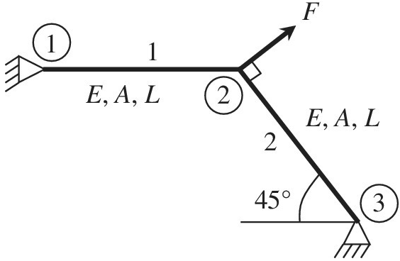
a. Compute the transformation matrix for elements 1 and 2.
b. Compute the element stiffness matrices for both elements in the global coordinate system.
c. Assemble the element stiffness matrices and force vectors to the structural matrix equation
d. Solve the FE equation after applying the boundary conditions. Write nodal displacements in the global coordinates.
e. Compute stress in element 1. Is it tensile or compressive?
Want to see the full answer?
Check out a sample textbook solution
Chapter 1 Solutions
Introduction To Finite Element Analysis And Design


- A frame moves along its n-axis a distance of 2 units and is then rotated about the o-axis an angle 60° followed by a rotation about the z-axis by 90°. It was then translated about the a-axis by 2 units and finally rotated about the x-axis by 45°. Construct the transformation matrix equation. Compute the total transformation performed by the frame. Compute the joint variables that had to be made if similar location and orientation were to be created using cylindrical and RPY configuration. The initial point is located at P=[5 3 4]^Tarrow_forwardii, If the length of each element is 5m and the k-EA/L is given as shown, analyze the following system by Direct Method of Finite Element. ki - 200 kN/m * - 1000 kN/m ky : 300 kN/m 400 kN 2 Develop the displacement vector b. Develop the force vectors | c. Develop the stifness matrix for each element d. Develop the global matrix for the sytem e. Find the displacement at node 2 £ Find the forces at node 1 and 3.arrow_forwardCompute the position and orientation of the tool point P from the given D-H table for the displacement variable e1=900 e2=90° and e3=90⁰. a1= 100 mm, a2= 100mm and a3 = 50mm Note: find the position and orientation using step by step procedure Present the roll, pitch, yaw and displacement in x,y and z axis. use the composite transformation matrix H-¹T₁= [ce; -se,ca; SO Sα₁ se, co,Ca; -C0₁Sα; 0 Sα₁ Cα₁ 0 0 0 aC0₁] aS0₂ d₁ 1 Joint 1 2 3 Figure 3 3-DOF (Industrial manipulator arm) 0 d α 0₁ 0 a1 02 0 a2 03 | 0 a³0 a -90 0arrow_forward
- Consider the following truss system. All bars are vertical or horizontal. Enter the elongation matrix (A = BT): (in the form "node 1: horiz", "node 1: vert", "node 2: horiz" etc.) A = Compute a basis for the nullspace of A. Basis = Match the following force vectors fm with the motions they would induce and state whether they are in the nullspace of A Motion: Motion: Motion: Motion: ? -1 In nullspace? In nullspace? In nullspace? In nullspace? -1 -2 -1 -1 -1 A B D (Click on a figure to enlarge it)arrow_forwardDraw the corresponding scheme and find the equation on the right. Method used and Four assumptions hA Tc.v.(t) = Taire + [Tc.v.(tt) – Tairele locp)"arrow_forwardConsider the following spring system. ////// m, _with spring constants c = 3 Assume down is the positive direction. Write the stiffness matrix K = 3. • Compute the external force which causes the displacement u = Force =arrow_forward
- Assigned necessary coordinate frames and obtained the total transformation matrix using the D-H method.arrow_forwardFigure 1 illustrates transformation involving a frame. Construct the transformation matrix of point C relative to point A.arrow_forward5. A leg is placed in traction to keep it elevated and prevent it from moving as shown: Small pulley i. What is the tension in the rope (recall: 30.0 one rope gliding through pulleys will have the same tension throughout)? 30.0 m=250 kg ii. With what is force , F, that is acting to pull on the foot and keep the leg under tension? Construct a vector diagram to assist with your solution.arrow_forward
- In the figure, we apply a transformation matrix to box A to obtain box B. (a) Derive the 3 x 3 homogeneous matrix that achieves the transformation in the figure. (b) Compute its inverse. B a A barrow_forward****USE MATLAB TO SOLVE THIS QUESTION**** 5. A composite cantilever beam, made of High Strength (HS) carbon/epoxy material with [04/304], plies, has uniformly applied load go. When qo=50N/m, length of the beam, L=0.1m, and width of the beam, b=0.05m. Find the maximum deflection of the beam. (for the HS carbon fiber/epoxy, E₁1 =131 GPa, E₂2= 11.2 GPa, V12 = 0.28, G12 = 6.55 GPa and ply thickness t=0.2mm) 90-50N/m Larrow_forwardPoints for stress vs strain (in image) Assume the compressive concrete strength (f’c) is 3,000 lb/in2 (psi)Calculate a cubic function (3rd order polynomial – Ax3+Bx2+Cx+Constant)Use this function to create a function that describes the slope of the cubic function (the derivative of thecubic function). This new function allows you to calculate the tangent to any point along the curve. Thetangent is the modulus of elasticity (E). The concrete code provides a formula to calculate E for concrete. That formula is:E = 57,000√??′, where f’c is in units of psi, and E is in units of psi.Use the derivative function you calculated to locate the point on the curve where the slope of the curvematches E using the concrete code formula. Express that stress point on the curve as a percentage ofthe compressive strength of the concrete. Now, calculate the secant modulus for the test case using 1,500 psi (50% f’c) as the arbitrary point onthe curve.Assume fracture occurs at the last point…arrow_forward
 Elements Of ElectromagneticsMechanical EngineeringISBN:9780190698614Author:Sadiku, Matthew N. O.Publisher:Oxford University Press
 Mechanics of Materials (10th Edition)Mechanical EngineeringISBN:9780134319650Author:Russell C. HibbelerPublisher:PEARSON
 Thermodynamics: An Engineering ApproachMechanical EngineeringISBN:9781259822674Author:Yunus A. Cengel Dr., Michael A. BolesPublisher:McGraw-Hill Education
 Control Systems EngineeringMechanical EngineeringISBN:9781118170519Author:Norman S. NisePublisher:WILEY
 Mechanics of Materials (MindTap Course List)Mechanical EngineeringISBN:9781337093347Author:Barry J. Goodno, James M. GerePublisher:Cengage Learning
 Engineering Mechanics: StaticsMechanical EngineeringISBN:9781118807330Author:James L. Meriam, L. G. Kraige, J. N. BoltonPublisher:WILEY