
Introduction To Finite Element Analysis And Design
2nd Edition
ISBN: 9781119078722
Author: Kim, Nam H., Sankar, Bhavani V., KUMAR, Ashok V., Author.
Publisher: John Wiley & Sons,
expand_more
expand_more
format_list_bulleted
Videos
Textbook Question
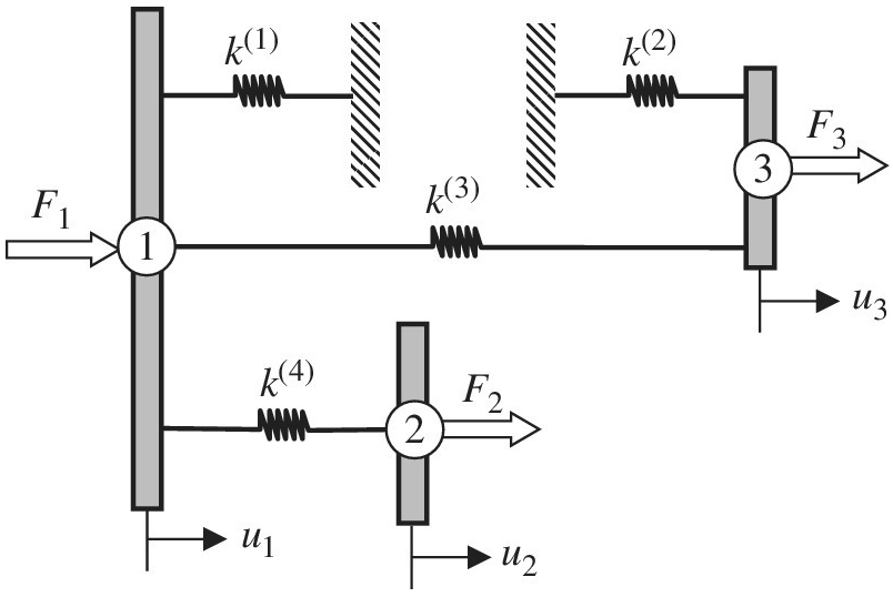
Chapter 1, Problem 9E
In the structure shown, rigid blocks are connected by linear springs. Imagine that only horizontal displacements are allowed. Write the global equilibrium equations
Expert Solution & Answer

Trending nowThis is a popular solution!

Students have asked these similar questions
Q: For the spring system shown in the accompanying figure, determine the
displacement of each node. Start by identifying the size of the global matrix.
Write down elemental stiffness matrices, and show the position of each
elemental matrix in the global matrix. Apply the boundary conditions and
loads. Solve the set of linear equations.
Also, compute the reaction forces.
k2 = 9 lb
k1 = 20b
in
20 lb
k,=5 lb
ww
lb
in
kz = 5 lb
in
ks = 9
in
lb
k6 = 9 in
50 lb
k4 = 20 lb
kg = 20 b
in
in
K1
For the spring shown above,
kl=100 N/mm, k2-200N/mm, k3-100N/mm, P-500N, ul-u3-0
Find:
1. The global stiffness matrix
2. Displacements of nodes 2 and 3
The figure below shows a beam supported by a spring while subjected to a horizontal force f.
The spring has a natural unstretched length 7 and stiffness constant k. The total length of the
beam is 3L, the force acts at 2L (see figure). The spring sits on vertical slider, such that it
remains horizontal at all times.
7
2L
(a) Find the equilibrium values of the angle 0 as a function of the parameters: k,L,1, and f.
(b) Let 1 = L and f = 4kL. Determine the stability of the solution at 0 = 0 and interpret the result.
(c) Using the other stationary value for the angle, verify that the moment of the applied force and
the spring about the pivot (bottom left) sum to zero.
Chapter 1 Solutions
Introduction To Finite Element Analysis And Design
Ch. 1 - Answer the following descriptive questions a....Ch. 1 - Calculate the displacement at node 2 and reaction...Ch. 1 - Repeat problem 2 by changing node numbers; that...Ch. 1 - Three rigid bodies, 2,3, and 4, are connected by...Ch. 1 - Three rigid bodies, 2,3, and 4, are connected by...Ch. 1 - Consider the spring-rigid body system described in...Ch. 1 - Four rigid bodies, 1, 2, 3, and 4, are connected...Ch. 1 - Determine the nodal displacements, element forces,...Ch. 1 - In the structure shown, rigid blocks are connected...Ch. 1 - The spring-mass system shown in the figure is in...
Ch. 1 - A structure is composed of two one-dimensional bar...Ch. 1 - Two rigid masses, 1 and 2, are connected by three...Ch. 1 - Use the finite element method to determine the...Ch. 1 - Consider a tapered bar of circular cross section....Ch. 1 - The stepped bar shown in the figure is subjected...Ch. 1 - Using the direct stiffness matrix method, find the...Ch. 1 - A stepped bar is clamped at one end and subjected...Ch. 1 - A stepped bar is clamped at both ends. A force of ...Ch. 1 - Repeat problem 18 for the stepped bar shown in the...Ch. 1 - The finite element equation for the uniaxial bar...Ch. 1 - The truss structure shown in the figure supports a...Ch. 1 - The properties of the two elements of a plane...Ch. 1 - For a two-dimensional truss structure as shown in...Ch. 1 - The 2D truss shown in the figure is assembled to...Ch. 1 - For a two-dimensional truss structure as shown in...Ch. 1 - The truss shown in the figure supports force Fat...Ch. 1 - Prob. 27ECh. 1 - In the finite element model of a plane truss in...Ch. 1 - Use the finite element method to solve the plane...Ch. 1 - The plane truss shown in the figure has two...Ch. 1 - Two bars are connected as shown in the figure....Ch. 1 - The truss structure shown in the figure supports...Ch. 1 - It is desired to use the finite element method to...Ch. 1 - Determine the member force and axial stress in...Ch. 1 - Determine the normal stress in each member of the...Ch. 1 - The space truss shown has four members. Determine...Ch. 1 - The uniaxial bar shown below can be modeled as a...Ch. 1 - In the structure shown below, the temperature of...Ch. 1 - Prob. 39ECh. 1 - The three-bar truss problem in figure 1.23 is...Ch. 1 - Use the finite element method to determine the...Ch. 1 - Repeat problem 41 for the new configuration with...Ch. 1 - Repeat problem 42 with an external force added to...Ch. 1 - The properties of the members of the truss in the...Ch. 1 - Repeat problem 44 for the truss on the right side...Ch. 1 - The truss shown in the figure supports the force ....Ch. 1 - The finite element method as used to solve the...Ch. 1 - Prob. 48E
Knowledge Booster


Learn more about
Need a deep-dive on the concept behind this application? Look no further. Learn more about this topic, mechanical-engineering and related others by exploring similar questions and additional content below.Similar questions
- Beam AB has a pin support at A and a roller support at B Joint B is also restrained by a linearly elastic rotational spring with stiffness kR, which provides a resisting moment MBdue to rotation at B. Member AB has flexural rigidity EI. A moment M0acts counterclockwise at B. Use the method of superposition to solve for all reactions. Find an expression for joint rotation Ain terms of spring stiffness kR. What is Awhen kR 0? What is Awhen kR— ? What is Awhen kR= 6EI/L?arrow_forwardA uniform bar AB of weight W = 25 N is supported by two springs, as shown in the figure. The spring on the left has a stiffness k[= 300 N/m and natural length Lt=250 mm. The corresponding quantities for the spring on the right are k2= 400 N/m and L^ = 200 mm. The distance between the springs is L = 350 mm, and the spring on the right is suspended from a support that is a distance it = SO mm below the point of support for the spring on the left. Neglect the weight of the springs. (a) At what distance x from the left-hand spring (figure part a) should a load P = 18 N be placed in order to bring the bar to a horizontal position? (b) If P is now removed, what new value of k{is required so that the bar (figure part a) will hang in a horizontal position underweight If? (c) If P is removed and kt= 300 N/m. what distance b should spring ktbe moved to the right so that the bar (figure part a) will hang in a horizontal position under weight II"? (d) If the spring on the left is now replaced by two springs in series (kt= 300 N/m, kt) with overall natural length Lt= 250 mm (see figure part b). what value of k; is required so that the bar will hang in a horizontal position under weight IF?arrow_forwardThe device shown in the figure consists of a prismatic rigid pointer ABC supported by a uniform translational spring of stiffness k = 950 N/m. The spring is positioned a distance P = 165 nun from the pinned end A of the pointer. The device is adjusted so that, when there is no load P, the pointer reads zero on the angular scale. (a) If the load P = 11 N, al what distance .v should the load be placed so that the pointer will read ?? = 2.5° on the scale (see figure part a)? (b) Repeal part (a) if a rotational spring E1= kb-6 is added al A (see figure part b). (c) Lel.x = 7b/8.What is P maxif 0 cannot exceed 2"? Include spring krin your analysis. (d) Now, if the weight of the pointer ABC is known to be W =3N and the weight or the spring is Ws= 2.75 N, what initial angular position (Left in degrees) of the pointer will result in a zero reading on the angular scale once the pointer is released from rest? Assume P = kr=0. (e) If the pointer is rotated lo a vertical position (see figure part c), find the required load P applied at mid-height of the pointer that will result in a pointer reading of 0 = 2.5" on the scale. Consider the weight of the pointer W. in your analysis.arrow_forward
- Repeat 1.3-9 but use the method of sections go find member forces in AC and BD.arrow_forwardConsider the spring assemblage shown, using the direct stiffness method do the following: 1. Write the global stiffness matrix 2. Determine the nodal displacements 3. Determine the nodal forces 4. Determine the reaction of supports K1 = 15 kN/m f Node 1 F = 0.675 kN K2 = 45 kN/m No Node 2 X positive to the right vov Node 3 K3 = 15 N/m Node 4arrow_forwardA- In each of the two plane structure (a,b) shown in Fig 1, rigid blocks are connected by linear spring. Imagine that only horizontal displacements are allowed. In each case, write the structure equilibrium equations [K]{D}= {R} in term of spring stiffness Ki, displacement degree of freedom ui, and applied load Fi. 5 (4) 2 4 (1) 3 (5) U5 F1 и, (2) Uz U4 Fs F2 F4arrow_forward
- b) A steel column AB is fixed at its base and is braced at its top by cables as shown in Figure Q4 (b). This column has moment of inertia of l= 113 x 10° mm and ly36.6 x 10° mm". If the length of column is 8 m, examine the allowable load, P that can be resisted by this column before it either begins to buckle or yields. Take modulus of elasticity, E = 200 GPa, yield stress, a, = 250 MPa, and factor of safety, F.S= 2.0. Given the cross-sectional area of this column is 12,700 mm. If the applied load P exceeded the allowable load, suggest TWO (2) methods of strengthening for this column. (CO2-PO2)(C6) !!arrow_forwardMember AB (helical spring) and Member AC (axial rod) are carrying a weight at point A. Member AB has the following properties: R = 90 mm, n -4 turns, G- 70 GPa, d- 30 mm, and Talow = 105 MPa while Member AC has the following properties: L= 2.A- 500 mm?, E = 200 GPa, and a low- 30 MPa. Determine the maximum safe %3D value of W (in N). Use simplified formula for the helical spring. A 60°arrow_forwardFor the spring assemblages shown in Figure, determine the nodal displacements, the forces in each element, and the reactions. Use the direct stiffness method for all problems. 500 kN/m 500 kN/m Figure P2-15 3 3 1 kN 1000 kN/m 1 kN warrow_forward
- Determine the nodal displacements, the forces in each element, and the reactions. Use the direct stiffness method fir these problem Figure P3-10 20 3 60 kN E = 210 GPa A = 3 × 10*m² 3 m 20 3 m 2.arrow_forwardTwo concentric springs of equal lengths are placed in an assembly shown below. A force P is applied against the plate above. Select all equations among the choices that hold true. No partial points. Note: P is force, ō is change in length. Pouter + Pinner = P Pouter = Pinner = P Souter = dinner douter #dinner P -Wwwandarrow_forwardTruck suspensions often have "helper springs" that engage at high loads. One such arrangement is a leaf spring with a helper coil spring mounted on the axle, as shown in the figure below. When the main leaf spring is compressed by distance yo, the helper spring engages and then helps to support any additional load. Suppose the leaf spring constant is 5.15 x 10⁵ N/m, the helper spring constant is 3.80 x 10⁵ N/m, and y₁ = 0.500 m. m Need Help? Truck body Main leaf spring (a) What is the compression of the leaf spring for a load of 4.90 x 10⁵ N? Read It -"Helper" spring Axle (b) How much work is done in compressing the springs?arrow_forward
arrow_back_ios
SEE MORE QUESTIONS
arrow_forward_ios
Recommended textbooks for you
 Mechanics of Materials (MindTap Course List)Mechanical EngineeringISBN:9781337093347Author:Barry J. Goodno, James M. GerePublisher:Cengage Learning
Mechanics of Materials (MindTap Course List)
Mechanical Engineering
ISBN:9781337093347
Author:Barry J. Goodno, James M. Gere
Publisher:Cengage Learning
Mechanical SPRING DESIGN Strategy and Restrictions in Under 15 Minutes!; Author: Less Boring Lectures;https://www.youtube.com/watch?v=dsWQrzfQt3s;License: Standard Youtube License