
Concept explainers
Videos
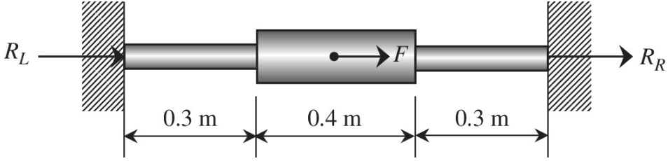
The stepped bar shown in the figure is subjected to a force at the center. Use the finite element method to determine the displacement at the center and reactions RL and RR.
Assume:
Want to see the full answer?
Check out a sample textbook solution
Chapter 1 Solutions
Introduction To Finite Element Analysis And Design
Additional Engineering Textbook Solutions
DeGarmo's Materials and Processes in Manufacturing
Engineering Mechanics: Statics & Dynamics (14th Edition)
Introduction to Heat Transfer
Fundamentals Of Thermodynamics
Thinking Like an Engineer: An Active Learning Approach (4th Edition)
Engineering Mechanics: Statics


- A bungee cord that behaves linearly elastically has an unstressed length L0= 760 mm and a stiffness k = 140 N/m. The cord is attached to two pegs, distance/? = 380 mm apart, and is pulled at its midpoint by a Force P = 80 N (see figure). (a) How much strain energy U is stored in the cord? (b) What is the displacement Scof the point where the load is applied? (c) Compare the strain energy (with the quantity PSC12. Note: The elongation of the cord is not small compared lo its original length.arrow_forwardA bar with a circular cross section having two different diameters d and 2d is shown in the figure. The length of each segment of the bar is L/2T and the modulus of elasticity of the material is E. (a) Obtain a formula for the strain energy U of the bar due to the load P. (b) Calculate the strain energy if the load P = 27 kN, the length L = 600 mm, the diameter d = 40 mm, and the material is brass with E = 105 GPa.arrow_forwardFigure below shows the bar with three equal elements. Use the finite element method and calculate: 2.1 the global stiffness matrix 2.2 the displacement on node 2, 3, 4 2.3 the Strain in each element 2.4 the stresses in each element using Hook's law and compare with theoretical stresses (o=F/A) (1) (2) (3) -50 N 10 mm 10 mm 10 mm A1=50 mm? A2=20 mm? A:=10 mm? E=200 GPaarrow_forward
- 4:50 Step 1 of 7 Done Consider the following diagram showing a rectangular steel bar supporting two overhanging loads: y 300 300 500 400 N 400 N В Bar, b=6, h=32arrow_forwardConsider a rigid rod that is subjected to two external forces and is fixed to the wall at A. The following figure displays the rod's free body diagram. Answer the following questions using the provided FBD. 2.5 -1 1 3.5 The support reaction at A along x-axis (A) is The support reaction at A along y-axis (Ay) is The support reaction at A along z-axis (A.) is The Moment reaction at support A about x-axis (Ma) is -1 n 1 0 -2.5 2.5 -1 -3.5 5.5 -5.5 -0.5 0.5 A₂ Mx4 Z M₂ My KN KN KN 3m KN.m 1m 1 KN 2m 2.5 KNarrow_forwardExample: 5 A rigid bar AB, 9 m long, is supported by two vertical rods at its end and in a horizontal position under a load P as shown in figure. Find the position of the load P so that the bar AB remains horizontal. 5 m A = 445 mm 2 %3D A = 1000 mm 2 %3D 9 m E = 1 x 10 5 3m E 3D 2 х 105 %3D A В Xarrow_forward
- Q3 An aluminum rod with modulus of elasticity, E = 70 GPa is fixed to the wall at both ends as shown in Figure 1.2. If the 10 kN force is applied at point 2, determine: i. the reaction forces at node 1 and 4, ii. the displacement at node 2 and 3. 2 10 kN 3 L= 400 mm L= 400 mm L= 400 mm A= 2000 mm² A= 600 mm² A= 600 mm²arrow_forwardA rigid beam is supported by a pin at A and two metallic wires at B and C. Determine the force P that causes the point C to displace downward by 0.1 mm. Given: E (wire B) = 200 Gpa, E (wire C)70 Gpa and both wires have a diameterD =6 mm. Consider a linear elastic behavior.A rigid beam is supported by a pin at A and two metallic wires at B and C. Determine the force P that causes the point C to displace downward by 0.1 mm. Given: E (wire B) = 200 Gpa, E (wire C)70 Gpa and both wires have a diameterD =6 mm. Consider a linear elastic behavior.arrow_forwardA rigid beam is supported by a pin at A and two metallic wires at B and C. Determine the force P that causes the point C to displace downward by 0.3 mm. Given: E (wire B) = 200 Gpa, E (wire C) = 70 Gpa and both wires have a diameter D=4 mm. Consider a linear elastic behavior. 2 m 1.5 m 3 m 2 m 2 m Select one: O P= 235 N OP= 294 N O P= 471 N P=157 Narrow_forward
- Q.2] Find the reactions at point A for the structure shown in the figure. z kN/m ++ A 10m 5m 20 KN #arrow_forwardFor the cantilever plane truss in the figure above, use MATLAB to determine: 1)Nodal displacements 2)Reaction Forces 3)Element Strains and Stresses Assuming that both supports are going to be fixed and the values of E = 70 GPa and A = 0.003125arrow_forwardA rigid beam is supported by a pin at A and two metallic wires at B and C. Determine the force P that causes the point C to displace downward by 0.3 mm. Given: E (wire B) = 70 Gpa, E (wire C) = 200 Gpa and both wires have a diameter D = 4 mm. Consider a linear elastic behavior. 2 m 1.5 m C A > < 3 m 2 m 2 m Select one: OP=537 N P = 597 N OP=430 N OP=287 N OP=D573 N Let's consider a rod having a solid circular cross-section with diameter of 4.mm and it is made of a material having a Young's modulusE= Barrow_forward
 Mechanics of Materials (MindTap Course List)Mechanical EngineeringISBN:9781337093347Author:Barry J. Goodno, James M. GerePublisher:Cengage Learning