
Concept explainers
Videos
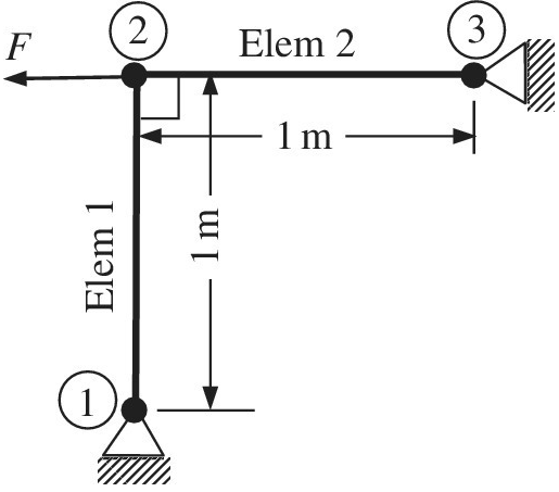
The properties of the two elements of a plane truss are given in the table below. Note that an external force of 10,000 N is acting on the truss at node 2.
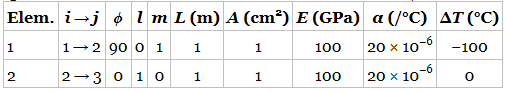
a. Write the thermal force vector for each element. Indicate row addresses clearly.
b. Assemble the thermal force
c. The problem was solved using FEA to obtain the displacements as
d. Show that equilibrium is satisfied at node 2.
Want to see the full answer?
Check out a sample textbook solution
Chapter 1 Solutions
Introduction To Finite Element Analysis And Design


- Question 5 A 120 mm x 100 mm x 20 mm T section short column is used as a simply supported beam. The beam carries the applied eccentric load F of 120 kN at the position indicated in Figure Q5. Start your calculations be setting an origin from the right-most point on the cross-section and determine the following: 100 120 mm F 20 mm 20 mm Figure Q5: T- section short column beam 5.1 The maximum compressive and tensile longitudinal direct stresses induced in the column. 5.2 Plot the stress distribution diagram and determine the position of the NA.arrow_forwardThe steel bolt of cross-sectional area A0 is placed inside the aluminum tube, also of cross-sectional area A0. The assembly is completed by making the nut ‘‘fingertight.’’ The dimensions of the reduced segment of the bolt (length b and cross-sectional area A) are designed so that the segment will yield when the temperature of the assembly is increased by 200°F. Write an algorithm that determines the relationship between A/A0 and b/L that satisfies this design requirement. Plot A=A0 against b/L from b/L = 0 to 1.0. Use the properties of steel and aluminum shown in the figure.arrow_forwardWhat is the size of the stiffness matrix of a 4-node quadrilateral element?arrow_forward
- A pushrod in the valve mechanism of an automotive engine has a nominal length of 203 mm. If the rod is made of SAE 4140 steel, compute the elongation due to a temperature change from -20°C to 140°C. TABLE 3-4 Coefficients of thermal expansion, a, for some t nd concrretearrow_forwardQuestion 5 A 120 mm x 100 mm x 20 mm T section short column is used as a simply supported beam. The beam carries the applied eccentric load F of 120 kN at the position indicated in Figure Q5. Start your calculations be setting an origin from the right-most point on the cross-ection and determine the following: 100 120 mm 20 mm F 20 mm Figure Q5: T- section short column beam 5.1 The maximum compressive and tensile longitudinal direct stresses induced in the column. 5.2 Mot the stress distribution diagram and determine the position of the NA.arrow_forward(Solid Mechanics) This finite element model is composed of 4 linear bar elements, each with a cross section of 10 mm² and material properties (E = 6 GPa, v=0.3). A weight of 200 N is applied and the nodes are named as shown below. (1) Compute the reaction forces. (2) What are the reaction forces when the weight is tripled to be 600 N? Find the solution without repeating the FEA. Explain why you can get the quick answer.arrow_forward
- Find the Global Stiffness Matrix and node displacements for the following BAR structurearrow_forwardPROBLEMFor the plane truss given below, using the Matrix Stiffness Analysis method, determine;• Determine displacements of the joints• Determine the forces in the truss members• Determine the support reactionsNote that the whole system has 4 nodes and hence 8 degrees of freedom. These degrees of freedomsare shown (in their positive directions) on the right hand side of the problem picture (1 to 8). So, thesystem stiffness matrix, K, will be 8x8 in size.Force and displacement units should be consistent (mm’s and N’s for example)arrow_forwardThe figure shows a rigid bar that is supported by a pin at A and two rods, one made of steel and the other of bronze. Neglecting the weight of the bar, compute the force (in N) in the steel rod caused by the 42758-Nload, using the following data: length of steel = 1.27 m, length of bronze = 2.06 m Area of steel = 522 mm, Area of bronze = 239 mm Modulus of elasticity of steel = 216 Gpa, Modulus of elasticity of bronze = 84 Gpa x= 0.69 m, y = 1.08 m, and z = 0.86 m. Round off the final answer to three decimal places. ... Bronze Steel Ey te zarrow_forward
- Part of a two story building is shown in the figure in which a concerte column and a steel column are used in the first and second floor. The compressive force on the roof of the second floor is PC = 370 kN. The compressive force on the first floor is PB = 420 kN. The steel [Esteel = 200 GPa] column is a wide angle steel shape that has a cross section area of A2 = 1950 mm2. The concrete [Econcrete = 30 GPa] column has a circular section with a diameter of d = 560 mm.[L1 = 5.6 m, L2 = 5.6 m] Using this equation FL/AEarrow_forwardThe figure shows a rigid bar that is supported by a pin at A and two rods, one made of steel and the other of bronze. Neglecting the weight of the bar, compute the force (in N) in the bronze rod caused by the 45846-Nload, using the following data: length of steel = 11 m, length of bronze = 2.3 m Area of steel = 562 mm, Area of bronze = 335 mm Modulus of elasticity of steel = 195 Gpa, Modulus of elasticity of bronze = 80 Gpa x= 0.55 m, y = 1.12 m, and z = 0.78 m. Round off the final answer to two decimal places. ... Bronze Steelarrow_forwardThe dimensions are of the graph are d1 = 7 cm , L1 = 6 m , d2 = 4.2 cm , and L2 = 5 m with applied loads F1 = 130 kN and F2 = 60 kN . The modulus of elasticity is E = 80 GPa . Use the following steps to find the deflection at point D. Point B is halfway between points A and C. What is the reaction force at A? Let a positive reaction force be to the right.arrow_forward
 Principles of Heat Transfer (Activate Learning wi...Mechanical EngineeringISBN:9781305387102Author:Kreith, Frank; Manglik, Raj M.Publisher:Cengage Learning