
Concept explainers
Videos
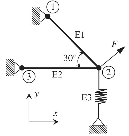
Two bars are connected as shown in the figure. Assume all joints are frictionless pin joints. At node 2, a vertical spring is connected as shown. Both bars are of length L and have the same properties: Young’s modulus = L and area of cross section = A. The spring stiffness = k.
a. Set up the stiffness matrices for the two truss elements and the spring element.
b. Assemble the stiffness matrices to form the global stiffness matrix.
c. Compute the deflections at node 2, if a force
Want to see the full answer?
Check out a sample textbook solution
Chapter 1 Solutions
Introduction To Finite Element Analysis And Design


- A simple structure is to be built to hold load at C as shown in Figure Q5. Body ABC is pin joint at wall A is regarded as a rigid body and is pin supported to rod BD at B. The respective dimensions are as shown in the figure. A support unit is to be connected by pin between point B and point D or point D' at the wall. a) Compare and analyze the two positions for the support unit not to fail by buckling when maximum load F is applied at C. Which position is the better choice between D and D' ? b) If load F is in opposite direction, what is the maximum load F that can be applied. (Properties of rod BD, E= 200GPA, G=77 GPa, v=0.3, o, = 250 MPa ) A 1.6m В 1.4m C 0.9m F 10mm 4mm D 0.8m 9. 15mm mm D' Crossection of Hollow Rod BD or BD'. ( 10mm x 15mm and 4mm x 9mm) Figure 05arrow_forwardLearning Goal: To solve for the support reactions of a frame. The frame shown in (Figure 1) is supported by a pin at A and a pin at D. The two members are connected by a pin at C. The dimensions are H₁ = 1.1 m, H₂ = 1.3 m, and L = 1 m. The applied force P = 11 kN acts at the midpoint of BC, and the distributed load has intensity w = 1.3 kN/m. Figure H1 B A P O W H₂arrow_forwardPROBLEMFor the plane truss given below, using the Matrix Stiffness Analysis method, determine;• Determine displacements of the joints• Determine the forces in the truss members• Determine the support reactionsNote that the whole system has 4 nodes and hence 8 degrees of freedom. These degrees of freedomsare shown (in their positive directions) on the right hand side of the problem picture (1 to 8). So, thesystem stiffness matrix, K, will be 8x8 in size.Force and displacement units should be consistent (mm’s and N’s for example)arrow_forward
- Find the Global Stiffness Matrix for the following Spring Structure. Use your answer to set up matrix Equation F=KX.arrow_forwardConsider the following truss system. All bars are vertical or horizontal. Enter the elongation matrix (A = BT): (in the form "node 1: horiz", "node 1: vert", "node 2: horiz" etc.) A = Compute a basis for the nullspace of A. Basis = Match the following force vectors fm with the motions they would induce and state whether they are in the nullspace of A Motion: Motion: Motion: Motion: ? -1 In nullspace? In nullspace? In nullspace? In nullspace? -1 -2 -1 -1 -1 A B D (Click on a figure to enlarge it)arrow_forwardFind the global stiffness matrix, displacement at node 1&2, reaction forces at 1&4, and force in spring for the following figure shown below. k1=90 N/mm, k2=1800 N/mm, k3=80 N/mm, P=600 N and u1=u4=0arrow_forward
- What is the size of the stiffness matrix of a 4-node quadrilateral element?arrow_forwardSolve the following with a free body diagram.arrow_forwardFind the stiffness matrices for each element and the large (general) set of equations of the system. (Start from the left when numbering the node points) (Start from the left when numbering the elements)arrow_forward
- A sign hangs from a wall, as shown. The upper left corner is supported by a pin joint, firmly attached to the wall. The upper right corner is supported by a rope. The rope is at a 30° angle from the horizontal. The pin joint is at the same height as the point where the sign attaches to the rope. The sign has a mass of 20kg. It is 2m long and the center-of- mass is 1m from the wall. a) Consider torques about the pin joint. Draw the line-of-action and lever-arm for both the tension force and the weight force. 1m c) What is the tension in the rope? mg b) What is the magnitude of the torque produced by the weight force about the pin joint? d) What are the reaction (support) forces at the pin joint? Write your answer as a vector. Y₁ 30° 2m -Xarrow_forwardA. The frame shown in Figure I is hinged to rigid supports at A and E. Find the values of: 1. Force components of Hinge A 2. Force components of Hinge B 3. Force in Member BC 4. Force in Member BD 크 트 A 5' 3' P = 600 15 FIGURE 1 DA 3' 3' Barrow_forwardThe dimensions are of the graph are d1 = 7 cm , L1 = 6 m , d2 = 4.2 cm , and L2 = 5 m with applied loads F1 = 130 kN and F2 = 60 kN . The modulus of elasticity is E = 80 GPa . Use the following steps to find the deflection at point D. Point B is halfway between points A and C. What is the reaction force at A? Let a positive reaction force be to the right.arrow_forward
 Elements Of ElectromagneticsMechanical EngineeringISBN:9780190698614Author:Sadiku, Matthew N. O.Publisher:Oxford University Press
 Mechanics of Materials (10th Edition)Mechanical EngineeringISBN:9780134319650Author:Russell C. HibbelerPublisher:PEARSON
 Thermodynamics: An Engineering ApproachMechanical EngineeringISBN:9781259822674Author:Yunus A. Cengel Dr., Michael A. BolesPublisher:McGraw-Hill Education
 Control Systems EngineeringMechanical EngineeringISBN:9781118170519Author:Norman S. NisePublisher:WILEY
 Mechanics of Materials (MindTap Course List)Mechanical EngineeringISBN:9781337093347Author:Barry J. Goodno, James M. GerePublisher:Cengage Learning
 Engineering Mechanics: StaticsMechanical EngineeringISBN:9781118807330Author:James L. Meriam, L. G. Kraige, J. N. BoltonPublisher:WILEY