
Introduction To Finite Element Analysis And Design
2nd Edition
ISBN: 9781119078722
Author: Kim, Nam H., Sankar, Bhavani V., KUMAR, Ashok V., Author.
Publisher: John Wiley & Sons,
expand_more
expand_more
format_list_bulleted
Concept explainers
Videos
Textbook Question
Chapter 1, Problem 44E
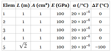
The properties of the members of the truss in the left side of the figure are given in the table. Calculate the nodal displacement and element forces. Show that force equilibrium is satisfied as node 3.
Expert Solution & Answer
Want to see the full answer?
Check out a sample textbook solution
Students have asked these similar questions
a beam is supported by a pin support at A and
a roller support at B. For this question, leave your answer in terms of
the variables w and L.
(a)
Using equilibrium of the full beam, find the support
forces at A and B.
(b)
First section: Make an arbitrary cut between points
A and B. Take the distance of the cut to be x along the beam
from point A. Draw the free-body diagram for the left section
and find functions for the internal shear force, V(x), and bending
moment, M(x), in the section of the beam between A and B.
(c)
Second section: Repeat part (b) for the section of the
beam between B and C. Take x to still be the distance from point
A.
(f)
Find the value of x at which V(x) = 0.
The internal bending moment reaches a maximum at
the same point as V(x) = 0. Find the maximum bending mo-
ment.
pin
Sketch the shear and bending moment diagrams.
B
L
W
C
roller
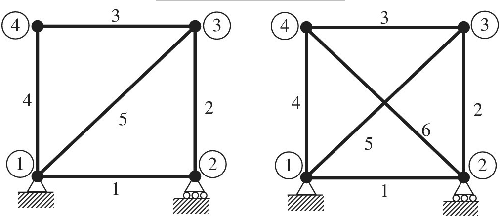
Find the force on each member of the truss and indicate if they are under tractionor compression.
I am having difficulty in the decompositions of forces. if you can, put this in detail.I already found the reaction forces and they are in the image below.
Thank you very much in advance
PROBLEM 3: A right-angled rigid pipe is fixed to a wall at A and is additionally supported through the cable CD as shown in the figure. The tension in the cable is 3 kN. Neglect the weight of the pipe. Use the Right-Hand-Rule to indicate the direction of the moment.
[8] Calculate total force reaction at A. (ANSWER: 3.00 KN)
[9] Calculate the moment reaction (including correct sign) at A about z-axis. (ANSWER: 2.168 KN-m)
[10] Calculate the moment reaction (including correct sign) at A about x-axis. (ANSWER: -0.843 KN-m)
Chapter 1 Solutions
Introduction To Finite Element Analysis And Design
Ch. 1 - Answer the following descriptive questions a....Ch. 1 - Calculate the displacement at node 2 and reaction...Ch. 1 - Repeat problem 2 by changing node numbers; that...Ch. 1 - Three rigid bodies, 2,3, and 4, are connected by...Ch. 1 - Three rigid bodies, 2,3, and 4, are connected by...Ch. 1 - Consider the spring-rigid body system described in...Ch. 1 - Four rigid bodies, 1, 2, 3, and 4, are connected...Ch. 1 - Determine the nodal displacements, element forces,...Ch. 1 - In the structure shown, rigid blocks are connected...Ch. 1 - The spring-mass system shown in the figure is in...
Ch. 1 - A structure is composed of two one-dimensional bar...Ch. 1 - Two rigid masses, 1 and 2, are connected by three...Ch. 1 - Use the finite element method to determine the...Ch. 1 - Consider a tapered bar of circular cross section....Ch. 1 - The stepped bar shown in the figure is subjected...Ch. 1 - Using the direct stiffness matrix method, find the...Ch. 1 - A stepped bar is clamped at one end and subjected...Ch. 1 - A stepped bar is clamped at both ends. A force of ...Ch. 1 - Repeat problem 18 for the stepped bar shown in the...Ch. 1 - The finite element equation for the uniaxial bar...Ch. 1 - The truss structure shown in the figure supports a...Ch. 1 - The properties of the two elements of a plane...Ch. 1 - For a two-dimensional truss structure as shown in...Ch. 1 - The 2D truss shown in the figure is assembled to...Ch. 1 - For a two-dimensional truss structure as shown in...Ch. 1 - The truss shown in the figure supports force Fat...Ch. 1 - Prob. 27ECh. 1 - In the finite element model of a plane truss in...Ch. 1 - Use the finite element method to solve the plane...Ch. 1 - The plane truss shown in the figure has two...Ch. 1 - Two bars are connected as shown in the figure....Ch. 1 - The truss structure shown in the figure supports...Ch. 1 - It is desired to use the finite element method to...Ch. 1 - Determine the member force and axial stress in...Ch. 1 - Determine the normal stress in each member of the...Ch. 1 - The space truss shown has four members. Determine...Ch. 1 - The uniaxial bar shown below can be modeled as a...Ch. 1 - In the structure shown below, the temperature of...Ch. 1 - Prob. 39ECh. 1 - The three-bar truss problem in figure 1.23 is...Ch. 1 - Use the finite element method to determine the...Ch. 1 - Repeat problem 41 for the new configuration with...Ch. 1 - Repeat problem 42 with an external force added to...Ch. 1 - The properties of the members of the truss in the...Ch. 1 - Repeat problem 44 for the truss on the right side...Ch. 1 - The truss shown in the figure supports the force ....Ch. 1 - The finite element method as used to solve the...Ch. 1 - Prob. 48E
Additional Engineering Textbook Solutions
Find more solutions based on key concepts
Comprehension Check 8-14
An 8-liter [L] container holds nitrogen (formula: N2. molecular weight = 28 grams per ...
Thinking Like an Engineer: An Active Learning Approach (3rd Edition)
55. The power required by an airplane is given by P = Fv, where P is the engine power, F is the thrust, and v i...
Thinking Like an Engineer: An Active Learning Approach (4th Edition)
A person applies an insect repellent onto an exposed area of A=0.5m2 of their body. The massof spray used is M=...
Fundamentals of Heat and Mass Transfer
1.1 What is the difference between an atom and a molecule? A molecule and a crystal?
Manufacturing Engineering & Technology
Solve Problem 3.24, but assume that the steam pressure in the cylinder starts at 1000kPa , dropping linearly wi...
Fundamentals Of Thermodynamics
The forces developed in each cable for equilibrium.
Engineering Mechanics: Statics & Dynamics (14th Edition)
Knowledge Booster


Learn more about
Need a deep-dive on the concept behind this application? Look no further. Learn more about this topic, mechanical-engineering and related others by exploring similar questions and additional content below.Similar questions
- Repeat 1.3-9 but use the method of sections go find member forces in AC and BD.arrow_forwardFind expressions for all support reaction Forces in the plane frame with load 3P applied at C as shown in the figure. Joints A and D are pin supported, and there is a roller support at joint F. The lengths and the properties of the members are shown in the figure. Neglect the weights of all members. Select Rfas the redundant.arrow_forwardThe inclined beam represents a ladder with the Following applied loads: the weight (W) of the house painter and the distributed weight (u) of the ladder itself. Find support reactions at A and B: then plot axial force (N), shear (V), and moment (M) diagrams. Label all critical N, V, and M values and also the distance to points where any critical ordmates are zero. Plot N, V, and M diagrams normal to the inclined ladder. Repeat part (a) for the case of the ladder suspended from a pin at B and traveling on a roller support perpendicular to the floor at A.arrow_forward
- Consider the plane truss with a pin support at joint 3 and a crtica1 roller support at joint 5 (see figure). (a) Find reactions at support joints 3 and 5. (b) Find axial forces in truss members 11 and 13.arrow_forwardFind support reactions at A and D and then calculate the axial force N, shear force V, and bending moment M at mid-span of AB. Let L = 14 ft, q0 = 12 lb/ft, P = 50 lb. and = 300 lb-ft.arrow_forwardSolve the preceding problem for the following data: b = 6 in., b = 10 in, L = 110 ft, tan a = 1/3, and q = 325 lb/ft.arrow_forward
- 1.3-15 A space truss is restrained at joints A, B, and C, as shown in the figure. Load 2P is applied at in the -x direction at joint A, load 3P acts in the + - direction at joint B. and load P is applied in the + r direction al joint C. Coordinates of all joints are given in terms of dimension variable L (see figure). (a) Find reaction force components Ayand Azin terms of load variable P. (b) Find the axial force in truss member AB in terms of load variable P.arrow_forwardA 150-lb rigid bar AB. with friction less rollers al each end. is held in the position shown in the figure by a continuous cable CAD. The cable is pinned at C and D and runs over a pulley at A. (a) Find reactions at supports A and B. (b) Find the force in the cable.arrow_forwardThe figure shows a wire cutter. Determine the cutting force on the wire at A when the 75-N forces are applied to the handgrips. (Hint: The horizontal components of pin forces at B and D are zero due to symmetry.)arrow_forward
- 2) The ABO vertical arm, whose weight of mass m is neglected in the figure, is kept in balance with a spherical joint to the wall with 3 cables. Calculate the reaction forces at point O and the force on all ropes. m=610 Please write the answer on a piece of paperarrow_forwardDetermine the displacement components at node 3 and the element forces for the plane truss shown in Figure P3-27. Let A =3 in and E =30 106 psi for all elements. Verify force equilibrium at node 3. 20 ft 3 5 kip Figure P3-27 10 kip 40 ft 30 ft 30 ft -arrow_forwardThe light boom AB is attached to a vertical wall by a ball and socket joint at A and supported by two cables at B. A force P is applied at B where P = 15i - 16j kN.Note that the reaction force at A acts along the boom because it is a two-force member. Calculate the magnitude of the reaction force at A in kN. Calculate the magnitude of the tension in cable BD in kN. Calculate the magnitude of the force in member BC in kN. Determine the magnitude of the moment of P about the x-axis in Nm. Determine the magnitude of the moment of P about the z-axis in Nm. Determine the magnitude of the moment of P about the origin (point O) in Nm.arrow_forward
arrow_back_ios
SEE MORE QUESTIONS
arrow_forward_ios
Recommended textbooks for you
 Mechanics of Materials (MindTap Course List)Mechanical EngineeringISBN:9781337093347Author:Barry J. Goodno, James M. GerePublisher:Cengage Learning
 International Edition---engineering Mechanics: St...Mechanical EngineeringISBN:9781305501607Author:Andrew Pytel And Jaan KiusalaasPublisher:CENGAGE L
Mechanics of Materials (MindTap Course List)
Mechanical Engineering
ISBN:9781337093347
Author:Barry J. Goodno, James M. Gere
Publisher:Cengage Learning
International Edition---engineering Mechanics: St...
Mechanical Engineering
ISBN:9781305501607
Author:Andrew Pytel And Jaan Kiusalaas
Publisher:CENGAGE L
EVERYTHING on Axial Loading Normal Stress in 10 MINUTES - Mechanics of Materials; Author: Less Boring Lectures;https://www.youtube.com/watch?v=jQ-fNqZWrNg;License: Standard YouTube License, CC-BY