
Introduction To Finite Element Analysis And Design
2nd Edition
ISBN: 9781119078722
Author: Kim, Nam H., Sankar, Bhavani V., KUMAR, Ashok V., Author.
Publisher: John Wiley & Sons,
expand_more
expand_more
format_list_bulleted
Videos
Textbook Question
Chapter 1, Problem 16E
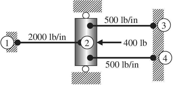
Using the direct stiffness matrix method, find the nodal displacements and the forces in each element and the reactions.
Expert Solution & Answer
Want to see the full answer?
Check out a sample textbook solution
Students have asked these similar questions
Compute the reactions for the following structure.
using E=young's modulus, I=moment of inertia
One-dimensional and three-node element Obtain the element stiffness matrix for
SOLVE STEP BY STEP IN DIGITAL FORMAT
DONT USE CHATGPT
For the following structures, calculate
-Reactions
-Deformation diagrams (individual and general)
(6)
7
100k/b
↓
+3ft
+
loft
80klb
T
+3ft +
Chapter 1 Solutions
Introduction To Finite Element Analysis And Design
Ch. 1 - Answer the following descriptive questions a....Ch. 1 - Calculate the displacement at node 2 and reaction...Ch. 1 - Repeat problem 2 by changing node numbers; that...Ch. 1 - Three rigid bodies, 2,3, and 4, are connected by...Ch. 1 - Three rigid bodies, 2,3, and 4, are connected by...Ch. 1 - Consider the spring-rigid body system described in...Ch. 1 - Four rigid bodies, 1, 2, 3, and 4, are connected...Ch. 1 - Determine the nodal displacements, element forces,...Ch. 1 - In the structure shown, rigid blocks are connected...Ch. 1 - The spring-mass system shown in the figure is in...
Ch. 1 - A structure is composed of two one-dimensional bar...Ch. 1 - Two rigid masses, 1 and 2, are connected by three...Ch. 1 - Use the finite element method to determine the...Ch. 1 - Consider a tapered bar of circular cross section....Ch. 1 - The stepped bar shown in the figure is subjected...Ch. 1 - Using the direct stiffness matrix method, find the...Ch. 1 - A stepped bar is clamped at one end and subjected...Ch. 1 - A stepped bar is clamped at both ends. A force of ...Ch. 1 - Repeat problem 18 for the stepped bar shown in the...Ch. 1 - The finite element equation for the uniaxial bar...Ch. 1 - The truss structure shown in the figure supports a...Ch. 1 - The properties of the two elements of a plane...Ch. 1 - For a two-dimensional truss structure as shown in...Ch. 1 - The 2D truss shown in the figure is assembled to...Ch. 1 - For a two-dimensional truss structure as shown in...Ch. 1 - The truss shown in the figure supports force Fat...Ch. 1 - Prob. 27ECh. 1 - In the finite element model of a plane truss in...Ch. 1 - Use the finite element method to solve the plane...Ch. 1 - The plane truss shown in the figure has two...Ch. 1 - Two bars are connected as shown in the figure....Ch. 1 - The truss structure shown in the figure supports...Ch. 1 - It is desired to use the finite element method to...Ch. 1 - Determine the member force and axial stress in...Ch. 1 - Determine the normal stress in each member of the...Ch. 1 - The space truss shown has four members. Determine...Ch. 1 - The uniaxial bar shown below can be modeled as a...Ch. 1 - In the structure shown below, the temperature of...Ch. 1 - Prob. 39ECh. 1 - The three-bar truss problem in figure 1.23 is...Ch. 1 - Use the finite element method to determine the...Ch. 1 - Repeat problem 41 for the new configuration with...Ch. 1 - Repeat problem 42 with an external force added to...Ch. 1 - The properties of the members of the truss in the...Ch. 1 - Repeat problem 44 for the truss on the right side...Ch. 1 - The truss shown in the figure supports the force ....Ch. 1 - The finite element method as used to solve the...Ch. 1 - Prob. 48E
Knowledge Booster


Learn more about
Need a deep-dive on the concept behind this application? Look no further. Learn more about this topic, mechanical-engineering and related others by exploring similar questions and additional content below.Similar questions
- Determine the nodal displacements, the forces in each element, and the reactions. Use the direct stiffness method fir these problem Figure P3-10 20 3 60 kN E = 210 GPa A = 3 × 10*m² 3 m 20 3 m 2.arrow_forward1. A beam of 200 kg mass is fixed at one end, is acted by two forces as shown in figure 1. Draw a free body diagram of the beam and find the reaction and the reactive moment at the fixed support. Use space below for your work. Writing just answers will get zero points. RA "A Show your work in this space 300 N k А 300 N 8marrow_forwardyou have a alloy. it has a 75GPa elastic moduls and it has been determined to have 215MPa of yeild strength. if your material has linear elastic stress-strain, figure out what the modulus of resiliance is for your alloy in J/m^3.arrow_forward
- Figure 2: Given the figure determine the reaction at C horizontal (Answer in whole number, indicate the answer in kN. just input the value, do this for all the questions on Figure 2)arrow_forward! How to compute the strain displacement matrix for each element?arrow_forward(Solid Mechanics) This finite element model is composed of 4 linear bar elements, each with a cross section of 10 mm² and material properties (E = 6 GPa, v=0.3). A weight of 200 N is applied and the nodes are named as shown below. (1) Compute the reaction forces. (2) What are the reaction forces when the weight is tripled to be 600 N? Find the solution without repeating the FEA. Explain why you can get the quick answer.arrow_forward
- Problem 2 Consider a plate formed by a homogeneous material with Young's modulus E, and Poisson's ratio v. The plate has total thickness h, the reference plane is located at the center of the plate, and N and Ny are applied at z = -h/2. Find the stiffness matrix of the plate.arrow_forwardPlease solve the question in Handwritten format with a complete free body diagram. (Also mention,How many reactions are present at A and D)arrow_forwardI understood for calculate reactions of equivalent determinate structure. I want to know how to draw diagram for axial,shear force and bending moments. Also the deformed shape of entire structurearrow_forward
- Figure 2 m 450 N 3 m 600 Nm 4 m 3 of 4 > Part D Complete previous part(s) Part E Identify the support reactions on the frame shown in (Figure 3). A is a roller and B is a pin. Check all the possible support reactions on the frame, even if some of them are equal to zero due to the loading given. Make sure the reactions in the set you choose do not depend on each other. Az O Ay OMA B₂ By OMB □ C₂ Cy O Mc оооооооос Submit Request Answerarrow_forwardFigure 1 below shows the bronze and galvani pipes are fastened to rigid supports at ends A and B and to a rigid plate C at their junction. The bronze pipe is twice as long as the galvani pipe. Two equal and symmetrically placed loads P act on the plate at C 1)Write one equilibrium equation involving reaction forces of the pipes with the help of free body diagram.[Note: Show all the forces acting on the members.] 2)Derive equilibrium equations for internal forces for section AC and BC with the help of respective free body diagrams.[Note: Show all the forces acting on the members.]arrow_forwardFree-Body Diagram Involving Internal Reactionsarrow_forward
arrow_back_ios
SEE MORE QUESTIONS
arrow_forward_ios
Recommended textbooks for you
 Elements Of ElectromagneticsMechanical EngineeringISBN:9780190698614Author:Sadiku, Matthew N. O.Publisher:Oxford University Press
 Mechanics of Materials (10th Edition)Mechanical EngineeringISBN:9780134319650Author:Russell C. HibbelerPublisher:PEARSON
 Thermodynamics: An Engineering ApproachMechanical EngineeringISBN:9781259822674Author:Yunus A. Cengel Dr., Michael A. BolesPublisher:McGraw-Hill Education
 Control Systems EngineeringMechanical EngineeringISBN:9781118170519Author:Norman S. NisePublisher:WILEY
 Mechanics of Materials (MindTap Course List)Mechanical EngineeringISBN:9781337093347Author:Barry J. Goodno, James M. GerePublisher:Cengage Learning
 Engineering Mechanics: StaticsMechanical EngineeringISBN:9781118807330Author:James L. Meriam, L. G. Kraige, J. N. BoltonPublisher:WILEY
Elements Of Electromagnetics
Mechanical Engineering
ISBN:9780190698614
Author:Sadiku, Matthew N. O.
Publisher:Oxford University Press
Mechanics of Materials (10th Edition)
Mechanical Engineering
ISBN:9780134319650
Author:Russell C. Hibbeler
Publisher:PEARSON
Thermodynamics: An Engineering Approach
Mechanical Engineering
ISBN:9781259822674
Author:Yunus A. Cengel Dr., Michael A. Boles
Publisher:McGraw-Hill Education
Control Systems Engineering
Mechanical Engineering
ISBN:9781118170519
Author:Norman S. Nise
Publisher:WILEY
Mechanics of Materials (MindTap Course List)
Mechanical Engineering
ISBN:9781337093347
Author:Barry J. Goodno, James M. Gere
Publisher:Cengage Learning
Engineering Mechanics: Statics
Mechanical Engineering
ISBN:9781118807330
Author:James L. Meriam, L. G. Kraige, J. N. Bolton
Publisher:WILEY
Mechanical SPRING DESIGN Strategy and Restrictions in Under 15 Minutes!; Author: Less Boring Lectures;https://www.youtube.com/watch?v=dsWQrzfQt3s;License: Standard Youtube License