
Videos
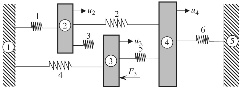
Three rigid bodies, 2,3, and 4, are connected by six springs as shown in the figure. The rigid walls are represented by 1 and 5. A horizontal force
Want to see the full answer?
Check out a sample textbook solution
Chapter 1 Solutions
Introduction To Finite Element Analysis And Design
Additional Engineering Textbook Solutions
Degarmo's Materials And Processes In Manufacturing
Heating Ventilating and Air Conditioning: Analysis and Design
Mechanics of Materials (10th Edition)
Automotive Technology: Principles, Diagnosis, And Service (6th Edition) (halderman Automotive Series)
Fox and McDonald's Introduction to Fluid Mechanics
Automotive Technology: Principles, Diagnosis, and Service (5th Edition)


- The L-shaped arm ABCD shown in the figure lies in a vertical plane and pivots about a horizontal pin at A. The arm has a constant cross-sectional area and total weight W. A vertical spring of stiffness k supports the arm at point B. (a) Obtain a formula for the elongation of the spring due to the weight of the arm. (b) Repeat part (a) if the pin support at A is moved to D.arrow_forwardSolve the preceding problem for the following data: b = 6 in., b = 10 in, L = 110 ft, tan a = 1/3, and q = 325 lb/ft.arrow_forwardA round bar ABC of length 2L (see figure) rotates about an axis through the midpoint C with constant angular speed w (radians per second). The material of the bar has weight density y. (a) Derive a formula for the tensile stress a’ in the bar as a function of the distance x from the midpoint C. (b) What is the maximum tensile stress a max?arrow_forward
- Solve the preceding problem for the following data: b = 8.0 in., k = 16 lb/in., a = 45°, and P = 10 lb.arrow_forwardA bar ABC revolves in a horizontal plane about a vertical axis at the midpoint C (see figure). The bar, which has a length 2L and crass-sectional area A, revolves at constant angular speed at. Each half of the bar (AC and BC) has a weight W, and supports a weight W2at its end. Derive the following formula for the elongation of one-half of the bar (that is. the elongation of either AC ar BC). =L223gEA(w1+3w2) in which E is t he modulus of elasticity of the material of the bar and g is the acceleration of gravity.arrow_forwardA uniform bar AB of weight W = 25 N is supported by two springs, as shown in the figure. The spring on the left has a stiffness k[= 300 N/m and natural length Lt=250 mm. The corresponding quantities for the spring on the right are k2= 400 N/m and L^ = 200 mm. The distance between the springs is L = 350 mm, and the spring on the right is suspended from a support that is a distance it = SO mm below the point of support for the spring on the left. Neglect the weight of the springs. (a) At what distance x from the left-hand spring (figure part a) should a load P = 18 N be placed in order to bring the bar to a horizontal position? (b) If P is now removed, what new value of k{is required so that the bar (figure part a) will hang in a horizontal position underweight If? (c) If P is removed and kt= 300 N/m. what distance b should spring ktbe moved to the right so that the bar (figure part a) will hang in a horizontal position under weight II"? (d) If the spring on the left is now replaced by two springs in series (kt= 300 N/m, kt) with overall natural length Lt= 250 mm (see figure part b). what value of k; is required so that the bar will hang in a horizontal position under weight IF?arrow_forward
- Repeat 1.3-9 but use the method of sections go find member forces in AC and BD.arrow_forwardA bumper for a mine car is constructed with a spring of stiffness k = 1120 lb/in. (see figure). If a car weighing 3450 lb is traveling at velocity v = 7 mph when it strikes the spring, what is the maximum shortening of the spring?arrow_forwardA circular bar ACB of a diameter d having a cylindrical hole of length .r and diameter till from A to C is held between rigid supports at A and B. A load P acts at U2from ends A and B. Assume E is constant. (a) Obtain formulas for the reactions R, and RBat supports A and B. respectively, due to the load P (see figure part a). (b) Obtain a formula for the displacement S at the point of load application (see figure part a). (c) For what value of x is RB= (6/5)?,? (See figure part a.) (d) Repeat part (a) if the bar is now rotated to a vertical position, load P is removed, and the bar is hanging under its own weight (assume mass density = p). (See figure part b.) Assume that x = LI2.arrow_forward
- Frame ABC has a moment release just left of joint B. Find axial force N, shear force V, and moment M at the top of column AB. Write variables N, V, and M in terms of variables P and L.arrow_forwardSolve the preceding problem if the collar has mass M = 80 kg, the height h = 0.5 m, the length L = 3.0 m, the cross-sectional area A = 350mm2. and the modulus of elasticity E = 170 GPa.arrow_forwardThe device shown in the figure consists of a prismatic rigid pointer ABC supported by a uniform translational spring of stiffness k = 950 N/m. The spring is positioned a distance P = 165 nun from the pinned end A of the pointer. The device is adjusted so that, when there is no load P, the pointer reads zero on the angular scale. (a) If the load P = 11 N, al what distance .v should the load be placed so that the pointer will read ?? = 2.5° on the scale (see figure part a)? (b) Repeal part (a) if a rotational spring E1= kb-6 is added al A (see figure part b). (c) Lel.x = 7b/8.What is P maxif 0 cannot exceed 2"? Include spring krin your analysis. (d) Now, if the weight of the pointer ABC is known to be W =3N and the weight or the spring is Ws= 2.75 N, what initial angular position (Left in degrees) of the pointer will result in a zero reading on the angular scale once the pointer is released from rest? Assume P = kr=0. (e) If the pointer is rotated lo a vertical position (see figure part c), find the required load P applied at mid-height of the pointer that will result in a pointer reading of 0 = 2.5" on the scale. Consider the weight of the pointer W. in your analysis.arrow_forward
 Mechanics of Materials (MindTap Course List)Mechanical EngineeringISBN:9781337093347Author:Barry J. Goodno, James M. GerePublisher:Cengage Learning