
Videos
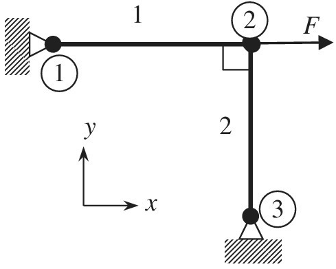
The truss shown in the figure supports the force
a. Write the
b. Assemble two elements and apply the boundary conditions to obtain the global matrix equation in the form of
c. Solve for the nodal displacements.
Want to see the full answer?
Check out a sample textbook solution
Chapter 1 Solutions
Introduction To Finite Element Analysis And Design
Additional Engineering Textbook Solutions
INTERNATIONAL EDITION---Engineering Mechanics: Statics, 14th edition (SI unit)
Manufacturing Engineering & Technology
Applied Fluid Mechanics (7th Edition)
Thinking Like an Engineer: An Active Learning Approach (4th Edition)
Applied Statics and Strength of Materials (6th Edition)
Engineering Mechanics: Statics


- The figure shows a bicycle wheel resting against a small step whose height is h = 0.100 m. The weight and radius of the wheel are W = 20.0 N and r = 0.390 m. A horizontal force is applied to the axle of the wheel. As the magnitude of increases, there comes a time when the wheel just begins to rise up and loses contact with the ground. What is the magnitude of the force when this happens? Number Units ✪ Farrow_forwardA cable spans a horizontal distance L = 67.0 ft , supports a uniform load w = 285 lb/ft , and has a sag h = 5.00 ft . (Figure 2) What are the minimum and maximum forces within the cable? Express the minimum and maximum forces within the cable numericaly to three significant figures in pounds separated by a comma. • View Available Hint(s) Figure V ΑΣφ It vec Tmin, Tmaz = lb Submit < Return to Assignment Provide Feedbackarrow_forwardCable 1 a A Cable 2 В y If the picture does not load, click this link. The shaded shape is supported by Cable 1 and Cable 2 in the position shown (Drawing is NOT to scale). The shape has a uniform weight per unit area of 11kN/m2. Step 1: If A=1.9m, C=0.4m, x=1.2m, y=1.7m, z=3.5m, a = 67°, and B = 18°, find the value of B %3D needed to keep the shape in static equilibrium. Then solve for the tension in Cable 1 (T1) and the tension in Cable 2 (T2). Once you have evaluated your values for B, T1 and T2 it is recommended that you redraw your free body diagram with the correct dimensions, weights, and forces T1x, T1y, T2x, T2y and confirm that you do have your problem correctly in horizontal, vertical, and moment equilibrium. Step 2: Once you have confirmed that you free body diagram is in equilibrium, solve the following equation: Z= T1+T2 Write your final answer for Z (in kN) in the answer box below. Round your answer to two decimal places.arrow_forward
- Of a column of infinite length to points A, B, C and D parallel FA, FB, FC and FD (kN) respectively Using the forces in the directions given in the figure, equivalent resultant force (FEŞ) size and application x and y (m) coordinates of the point find. FA=20 FB=55 FC=35 FD=77 xA=13 yA=8 xB=3 yB=5 xC=10 yC=0 xD=-9 yD=-15arrow_forwardOP •C h W The man in the diagram is trying to move a large box by pushing on it with a force, P. The box weighs 300 N and its centre of gravity is located in the centre of the box (point C). Given: a = 1.8 m b = 0.8 m h= 0.9 m What is the minimum force that will cause the box to tip? Please include the unit ("N") within your answer and round to 3 significant figures (e.g. if the calculated answer was 55.562 Newtons please input: 55.6 N). Answer: What is the minimum coefficient of static friction that will permit tipping to occur? Please do not include the unit s (as there are none) within your answer and round to 3 significant figures (e.g. if the calculated answer was 55.562 please input: 55.6). Answer:arrow_forwardReview Learning Goal: To use the vector cross product to calculate the moment produced by a force, or forces, about a specified point on a member. Part A - Moment due to a force specified by magnitude and endpoints The moment of a force F about the moment axis passing through O and perpendicular to the plane containing O and F can be expressed using the vector cross product, Mo =r x F. In a properly constructed Cartesian coordinate system, the vector cross product can be calculated using a matrix determinant: As shown, a member is fixed at the origin, point O, and has an applied force F, the tension in the rope, applied at the free end, point B. (Figure 1) The force has magnitude F = 180 N and is directed as shown. The dimensions are ¤1 = 0.350 m, x2 = 1.90 m, y1 = 2.30 m, and z1 = 1.20 m. What is the moment about the origin due to the applied force F? i j M =rx F =|rz k Express the individual components of the Cartesian vector to three significant figures, separated by commas. ry F F,…arrow_forward
- Example ( 2-1) : The ring in the figure below is subjected to two forces ( F1) and ( F2). Determine the magnitude and direction of the resultant force. 10° F, = 150 N F = 100 N %3D 15° Solution : Parallelogram Law. The parallelogram is formed by drawing a line from the head of F1 that is parallel to F2 , and another line from the head of F2 that is parallel to F1 , the resultant force FR extends to where these lines intersect at point A. The two unknowns are the magnitude of ( FR) and the angle ( 0) (theta).arrow_forwardASAParrow_forwardFigure A1 below represents a system of three linear springs attached to a wall. The system is subjected to three uniaxial forces at nodes 1, 2 and 3 respectively | kı k₂ [K] = F₁ k3 Figure Al (a) Prove the stiffness of the system is (show your workings) [k₁ + k₂ -k₂ 0 F₂ -K₂ 0 k₂ + K3-K3 -k3 K3 3 F3arrow_forward
- A weightless rectangular bar BDC is loaded as shown below. There is a smooth pin at point C, a 100 N force at point D and a cable at point B. The bar and all forces are in the plane of the page (2D case). A F = 100 N 2 m 50° C 2 m 2 m 4 m a) Write the 100 N force using polar vector representation: F = |F| N@ angle 0 CCW from +x to the right. Calculate the angle theta in degrees. b) Calculate the moment of the 100 N force about point C. Give your answer in N-m (newton- meter). c) What should the direction of the 100 N force be to produce a zero moment about point B? Calculate and report the smallest angle in degrees CCW from +x to the right (angle in standard position). d) What should the direction of the 100 N force be to produce a zero moment about point A? Calculate and report the smallest angle in degrees CCW from +x to the right (angle in standard position).arrow_forwardDraw the Shear force diagram & Bending moment diagram for the cantilever beam as shown in figure, mark the salient points in the diagram. Neglect the self-weight of the beam, where F1 =10 N, F2 =60N, F3 =30 N, F4 =1ON, a =5 m, b=2 m, c=3 m, d=5 m F4 F3 F2 F1 E A d. aarrow_forward:Q81 The moment M for the force the figure shown below is 250 N 153 -200 mm 30 mm 46.5 N.M O 46.6 N.M O 46.4N. M of L isarrow_forward
 Elements Of ElectromagneticsMechanical EngineeringISBN:9780190698614Author:Sadiku, Matthew N. O.Publisher:Oxford University Press
 Mechanics of Materials (10th Edition)Mechanical EngineeringISBN:9780134319650Author:Russell C. HibbelerPublisher:PEARSON
 Thermodynamics: An Engineering ApproachMechanical EngineeringISBN:9781259822674Author:Yunus A. Cengel Dr., Michael A. BolesPublisher:McGraw-Hill Education
 Control Systems EngineeringMechanical EngineeringISBN:9781118170519Author:Norman S. NisePublisher:WILEY
 Mechanics of Materials (MindTap Course List)Mechanical EngineeringISBN:9781337093347Author:Barry J. Goodno, James M. GerePublisher:Cengage Learning
 Engineering Mechanics: StaticsMechanical EngineeringISBN:9781118807330Author:James L. Meriam, L. G. Kraige, J. N. BoltonPublisher:WILEY