
Introduction To Finite Element Analysis And Design
2nd Edition
ISBN: 9781119078722
Author: Kim, Nam H., Sankar, Bhavani V., KUMAR, Ashok V., Author.
Publisher: John Wiley & Sons,
expand_more
expand_more
format_list_bulleted
Concept explainers
Videos
Textbook Question
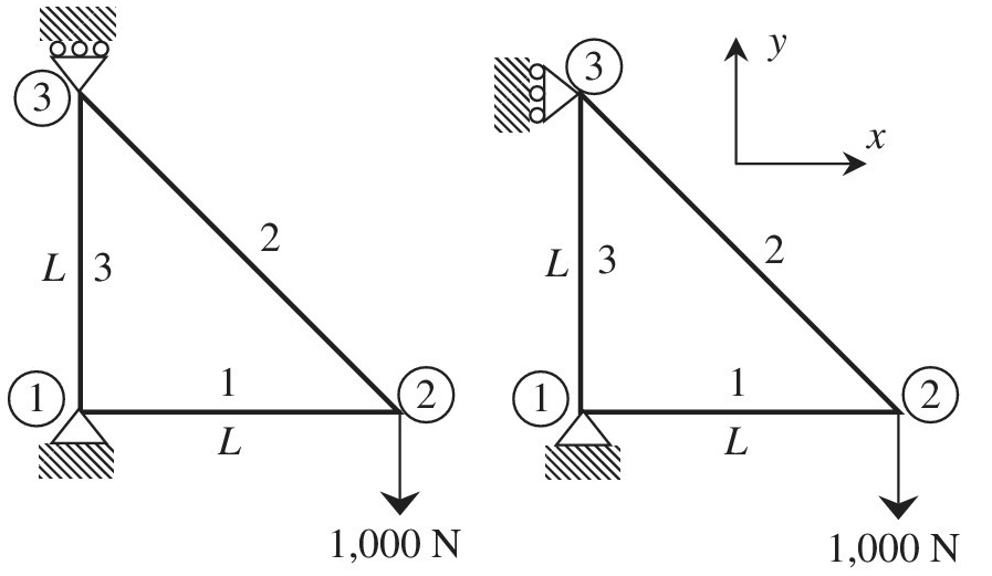
Chapter 1, Problem 33E
It is desired to use the finite element method to solve the two plane miss problems shown in the figure below. Assume
Expert Solution & Answer
Want to see the full answer?
Check out a sample textbook solution
Students have asked these similar questions
2) The vertices of a wedge are given in the matrix show below. Rotate the wedge 30* CCW around
the x-axis and then 45° CW around the y-axis.
r0 0 0
0 0
11
4 0 0
[P]
4 0 2
0 3
o 3
0.
Express the following in complex exponential form:
x[cos(yo)+jsin(yo)]
Where x = 8 and y = 166.
State the argument in radians.
****USE MATLAB TO SOLVE
THIS
QUESTION****
5. A composite cantilever beam, made of High Strength (HS) carbon/epoxy material
with [04/304], plies, has uniformly applied load go. When qo=50N/m, length of the
beam, L=0.1m, and width of the beam, b=0.05m. Find the maximum deflection of
the beam.
(for the HS carbon fiber/epoxy, E₁1 =131 GPa, E₂2= 11.2 GPa, V12 = 0.28, G12 = 6.55 GPa
and ply thickness t=0.2mm)
90-50N/m
L
Chapter 1 Solutions
Introduction To Finite Element Analysis And Design
Ch. 1 - Answer the following descriptive questions a....Ch. 1 - Calculate the displacement at node 2 and reaction...Ch. 1 - Repeat problem 2 by changing node numbers; that...Ch. 1 - Three rigid bodies, 2,3, and 4, are connected by...Ch. 1 - Three rigid bodies, 2,3, and 4, are connected by...Ch. 1 - Consider the spring-rigid body system described in...Ch. 1 - Four rigid bodies, 1, 2, 3, and 4, are connected...Ch. 1 - Determine the nodal displacements, element forces,...Ch. 1 - In the structure shown, rigid blocks are connected...Ch. 1 - The spring-mass system shown in the figure is in...
Ch. 1 - A structure is composed of two one-dimensional bar...Ch. 1 - Two rigid masses, 1 and 2, are connected by three...Ch. 1 - Use the finite element method to determine the...Ch. 1 - Consider a tapered bar of circular cross section....Ch. 1 - The stepped bar shown in the figure is subjected...Ch. 1 - Using the direct stiffness matrix method, find the...Ch. 1 - A stepped bar is clamped at one end and subjected...Ch. 1 - A stepped bar is clamped at both ends. A force of ...Ch. 1 - Repeat problem 18 for the stepped bar shown in the...Ch. 1 - The finite element equation for the uniaxial bar...Ch. 1 - The truss structure shown in the figure supports a...Ch. 1 - The properties of the two elements of a plane...Ch. 1 - For a two-dimensional truss structure as shown in...Ch. 1 - The 2D truss shown in the figure is assembled to...Ch. 1 - For a two-dimensional truss structure as shown in...Ch. 1 - The truss shown in the figure supports force Fat...Ch. 1 - Prob. 27ECh. 1 - In the finite element model of a plane truss in...Ch. 1 - Use the finite element method to solve the plane...Ch. 1 - The plane truss shown in the figure has two...Ch. 1 - Two bars are connected as shown in the figure....Ch. 1 - The truss structure shown in the figure supports...Ch. 1 - It is desired to use the finite element method to...Ch. 1 - Determine the member force and axial stress in...Ch. 1 - Determine the normal stress in each member of the...Ch. 1 - The space truss shown has four members. Determine...Ch. 1 - The uniaxial bar shown below can be modeled as a...Ch. 1 - In the structure shown below, the temperature of...Ch. 1 - Prob. 39ECh. 1 - The three-bar truss problem in figure 1.23 is...Ch. 1 - Use the finite element method to determine the...Ch. 1 - Repeat problem 41 for the new configuration with...Ch. 1 - Repeat problem 42 with an external force added to...Ch. 1 - The properties of the members of the truss in the...Ch. 1 - Repeat problem 44 for the truss on the right side...Ch. 1 - The truss shown in the figure supports the force ....Ch. 1 - The finite element method as used to solve the...Ch. 1 - Prob. 48E
Knowledge Booster


Learn more about
Need a deep-dive on the concept behind this application? Look no further. Learn more about this topic, mechanical-engineering and related others by exploring similar questions and additional content below.Similar questions
- What is an element by element operation in matlab?arrow_forward- Python 3 (pyke We have learned the mid-point and trapezoidal rule for numercial intergration in the tutorials. Now you are asked to implement the Simpson rule, where we approximate the integration of a non-linear curve using piecewise quadratic functions. Assume f(x) is continuous over [a, b]. Let [a, b] be divided into N subintervals, each of length Ax, with endpoints at P= x0, x1,x2,..., Xn,...,xN. Each interval is Ax = (b-a)/N. $ The equation for the Simpson numerical integration rule is derived as: df(xn)) + 2 (Σ=2n even Now complete the Python function InterageSimpson (N, a, b) below to implement this Simpson rule using the above equation. The function to be intergrate is f(x) = 2x³ (Already defined in the function, no need to change). Sof(x)dx≈ [f(x) + 4 (N= []: 'Complete the function given the variables N, a,b and return the value as "TotalArea". " "Don't change the predefined content only fill your code in the region 'YOUR CODE" a Idle Mem: 262.63/12288.00 MB F4 R from math…arrow_forwardFor the following system, find the mass matrix [m] and stiffness matrix [k] and write the differential equations.arrow_forward
- sn3 Read and analyze the following questions and answer themvery carefully. Show your complete (show unit cancellation)and step-by-step solution and box your final answer. Use threedecimal places.arrow_forwardConsider the robotic arm placed on the zy-place as shown below. Let O be the origin and assume that joint A is on the y-axis. It is given that |OA|-0.6 m. |AB|-1.3 m, IBC) - 1.7 m, ICD-1.2 m, [DE] -0.4 m, ZOAB 160°, ZABC-43° and ZBCD-120°. It is also given that DE || OA. Answer the following. a. Find the direction angle of CD in standard position. Direction angle b. Find ZCDE. ZCDE- c. Find the horizontal distance h and the vertical distance e between O and E. Round your answers to at least 2 decimal places. h- ******** m marrow_forwardConsider the figure as shown below. 2.1 Please describe [A, B, C, D] and [A', B', C', D'] in frame XOY as matrix form. 2.2 Please get transformation matrix of T, T, T. Y 3 2 O 3 B' Y₁ D 5 1 B X₁ Xarrow_forward
- What is the error in the following code: x=[1:1:10]; y=[ 21 33 4 56 77 88 990 ; semilogy (x, y,'r--'); vectors must be the same lengths can't draw by semilogy x in not a vector there is no any error matlab (w = [1 0-9; 2 -2 0; 1 2 3]; ). What is the value of x(2,1) ? undefined O 2 O the whole second rowarrow_forward1 Write the real value of the following number which are represented in 2's complement . (1) 1111 1111 2 (4578) D= ( ) BCD 3 Write their ASCII code(in hex form): В, b, 6 4 Write their binary, 1's complement and 2's complemer (for a 8-bit CPU) (2) 1000 0000 (3) 0110 1101 15, -20 5 What is the range of a unsigned 8-bit integer? What is th range of a signed 8-bit number in 2's complement ? 6 What is the range of a unsigned 16-bit integer? What is tł range of a signed 16-bit number in 2's complement ?arrow_forward2) Find the value of x :- 2 1 [x 4 1]] 1 2 = 0 2 1 ans. : x= ) or x= 1arrow_forward
- Draw the corresponding scheme and find the equation on the right. Method used and Four assumptions hA Tc.v.(t) = Taire + [Tc.v.(tt) – Tairele locp)"arrow_forwardA = (A1)ï+ (A2)J + (A3)k A = 2, B = 3 B = (B1)ï + (B2)J + (B3)k ĀxB = ? Ā.B= ? JÃ×B]= ?arrow_forwardConsider the figure as shown below. O-XoYoZo is the reference frame and O-X₁Y₁Z₁ is the frame attached to the tool. Sketch the tool position after each intermediate position of the operation of the tool about the reference frame: roll π/2(rotate about Zo), pitch -T/2(rotate about Yo), yaw π/2(rotate about Xo). Please write the final rotation matrix expression. ZI,Zo XI,Xo Yı, Yoarrow_forward
arrow_back_ios
SEE MORE QUESTIONS
arrow_forward_ios
Recommended textbooks for you
 Elements Of ElectromagneticsMechanical EngineeringISBN:9780190698614Author:Sadiku, Matthew N. O.Publisher:Oxford University Press
 Mechanics of Materials (10th Edition)Mechanical EngineeringISBN:9780134319650Author:Russell C. HibbelerPublisher:PEARSON
 Thermodynamics: An Engineering ApproachMechanical EngineeringISBN:9781259822674Author:Yunus A. Cengel Dr., Michael A. BolesPublisher:McGraw-Hill Education
 Control Systems EngineeringMechanical EngineeringISBN:9781118170519Author:Norman S. NisePublisher:WILEY
 Mechanics of Materials (MindTap Course List)Mechanical EngineeringISBN:9781337093347Author:Barry J. Goodno, James M. GerePublisher:Cengage Learning
 Engineering Mechanics: StaticsMechanical EngineeringISBN:9781118807330Author:James L. Meriam, L. G. Kraige, J. N. BoltonPublisher:WILEY
Elements Of Electromagnetics
Mechanical Engineering
ISBN:9780190698614
Author:Sadiku, Matthew N. O.
Publisher:Oxford University Press
Mechanics of Materials (10th Edition)
Mechanical Engineering
ISBN:9780134319650
Author:Russell C. Hibbeler
Publisher:PEARSON
Thermodynamics: An Engineering Approach
Mechanical Engineering
ISBN:9781259822674
Author:Yunus A. Cengel Dr., Michael A. Boles
Publisher:McGraw-Hill Education
Control Systems Engineering
Mechanical Engineering
ISBN:9781118170519
Author:Norman S. Nise
Publisher:WILEY
Mechanics of Materials (MindTap Course List)
Mechanical Engineering
ISBN:9781337093347
Author:Barry J. Goodno, James M. Gere
Publisher:Cengage Learning
Engineering Mechanics: Statics
Mechanical Engineering
ISBN:9781118807330
Author:James L. Meriam, L. G. Kraige, J. N. Bolton
Publisher:WILEY
The Robot Revolution: The New Age of Manufacturing | Moving Upstream; Author: Wall Street Journal;https://www.youtube.com/watch?v=HX6M4QunVmA;License: Standard Youtube License