
Introduction To Finite Element Analysis And Design
2nd Edition
ISBN: 9781119078722
Author: Kim, Nam H., Sankar, Bhavani V., KUMAR, Ashok V., Author.
Publisher: John Wiley & Sons,
expand_more
expand_more
format_list_bulleted
Concept explainers
Videos
Textbook Question
Chapter 1, Problem 11E
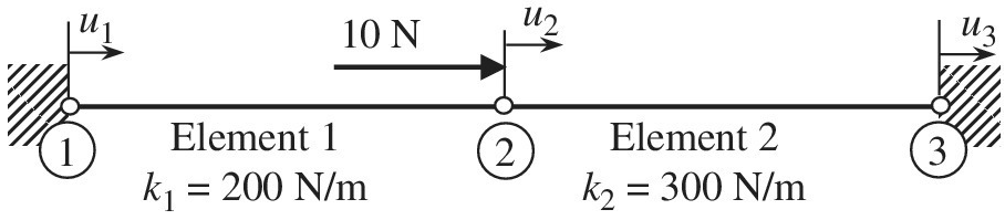
A structure is composed of two one-dimensional bar elements. When a 10 N force is applied to node 2, calculate the displacement
Expert Solution & Answer
Want to see the full answer?
Check out a sample textbook solution
Students have asked these similar questions
An L-shaped bracket is supported by a frictionless pin at A and a cable between points B and D. If pin A is the origin, point C is at (-7, 0); and pin B is at (-7, -10). The cable is attached between point B and an anchor at point D, at (-2, -14). Units are in feet. Force F acts at point C at an angle of 60o from the positive x-axis. Determine the magnitude of the moment that the force F produces about point A. Determine the tension required to hold the bracket in position.
Find the Global Stiffness Matrix for the following Spring Structure. Use your
answer to set up matrix Equation F=KX.
2
-3 5]
Q-8: Find det(B), if b =
=| 1
3
%3D
1
-2 2.
Chapter 1 Solutions
Introduction To Finite Element Analysis And Design
Ch. 1 - Answer the following descriptive questions a....Ch. 1 - Calculate the displacement at node 2 and reaction...Ch. 1 - Repeat problem 2 by changing node numbers; that...Ch. 1 - Three rigid bodies, 2,3, and 4, are connected by...Ch. 1 - Three rigid bodies, 2,3, and 4, are connected by...Ch. 1 - Consider the spring-rigid body system described in...Ch. 1 - Four rigid bodies, 1, 2, 3, and 4, are connected...Ch. 1 - Determine the nodal displacements, element forces,...Ch. 1 - In the structure shown, rigid blocks are connected...Ch. 1 - The spring-mass system shown in the figure is in...
Ch. 1 - A structure is composed of two one-dimensional bar...Ch. 1 - Two rigid masses, 1 and 2, are connected by three...Ch. 1 - Use the finite element method to determine the...Ch. 1 - Consider a tapered bar of circular cross section....Ch. 1 - The stepped bar shown in the figure is subjected...Ch. 1 - Using the direct stiffness matrix method, find the...Ch. 1 - A stepped bar is clamped at one end and subjected...Ch. 1 - A stepped bar is clamped at both ends. A force of ...Ch. 1 - Repeat problem 18 for the stepped bar shown in the...Ch. 1 - The finite element equation for the uniaxial bar...Ch. 1 - The truss structure shown in the figure supports a...Ch. 1 - The properties of the two elements of a plane...Ch. 1 - For a two-dimensional truss structure as shown in...Ch. 1 - The 2D truss shown in the figure is assembled to...Ch. 1 - For a two-dimensional truss structure as shown in...Ch. 1 - The truss shown in the figure supports force Fat...Ch. 1 - Prob. 27ECh. 1 - In the finite element model of a plane truss in...Ch. 1 - Use the finite element method to solve the plane...Ch. 1 - The plane truss shown in the figure has two...Ch. 1 - Two bars are connected as shown in the figure....Ch. 1 - The truss structure shown in the figure supports...Ch. 1 - It is desired to use the finite element method to...Ch. 1 - Determine the member force and axial stress in...Ch. 1 - Determine the normal stress in each member of the...Ch. 1 - The space truss shown has four members. Determine...Ch. 1 - The uniaxial bar shown below can be modeled as a...Ch. 1 - In the structure shown below, the temperature of...Ch. 1 - Prob. 39ECh. 1 - The three-bar truss problem in figure 1.23 is...Ch. 1 - Use the finite element method to determine the...Ch. 1 - Repeat problem 41 for the new configuration with...Ch. 1 - Repeat problem 42 with an external force added to...Ch. 1 - The properties of the members of the truss in the...Ch. 1 - Repeat problem 44 for the truss on the right side...Ch. 1 - The truss shown in the figure supports the force ....Ch. 1 - The finite element method as used to solve the...Ch. 1 - Prob. 48E
Knowledge Booster


Learn more about
Need a deep-dive on the concept behind this application? Look no further. Learn more about this topic, mechanical-engineering and related others by exploring similar questions and additional content below.Similar questions
- 2000Lbs 30° 60° y A' \ B The bar OA is fully constrained at O and attached to the cable AB. The bar length is 20', and it forms a 30° angle with the z-axis and its projection on the x– y plane forms a 60° angle with the x-axis. The point B is prescribed by the coordinates (8',16',0). If the force in the cable is 2000Lbs, what is the moment of this force about O? What is the moment of the 2000Lbs force about the axis OÁ.arrow_forwardA. Find the values of a such that vectors and are orthogonal. B. Find the domains of the vector-valued function 7(t) = e' i+ j+ In(t? – 4) karrow_forwardcalculated using a matrix determinant: Part C - Moment due to two forces i j k M =r x F =| rz ry As shown, a member is fixed at the origin, point O, and has two applied forces, F1 and F2, applied at the free end, rz F, F, F point B. (Figure 3) Notice that the order of the elements of the matrix determinant is important; switching rows 2 and 3 of the determinant would change the sign of the moment from positive to negative (or vice versa.) The forces are given by F1 = 115 Ni- 110 Nj+ 55 N k and F2 has magnitude 195 N and direction angles a = 143.0°, B= 57.0°, and y= 75.2°. The dimensions are x1 = 1.30 m, y1 = 1.85 m, and z1 = 1.10 m. What is the moment about the origin due to the applied forces? Figure 3 of 3 Express the individual components of the Cartesian vector to three significant figures, separated by commas. • View Available Hint(s) vec ? Mo =[ i, j, k] N. m Submit В < Return to Assignment Provide Feedbackarrow_forward
- For the spring system shown in the above figure, determine the displacement of each node. In the figure, the unit for the stiffness k is pound (lb) per inch. The left side of the system is fixed to a rigid wall, while the right side is displaced 0.5 inch to the right. Put a node between the rigid wall on the left and spring 1. Use the element method to establish the element stiffness matrix and then the global stiffness matrix. Apply the boundary conditions and theloads (by modifying the appropriate rows of the matrix and load vector). Solve the set of linear equations either by hand or using Matlab, Mathcad or Maple.arrow_forward1- In space ,the point can be specified by position vector r wnich is given by: A:r-ix+ jy c r=ix+ jy + kz B:r=ix+ D:r=ixarrow_forwardusing laplace s domainarrow_forward
- 3 points are plotted in the x, y, & z-plane as follows: A(-1,0,3); B(4, 2, 0); C(0,-1,-1). Establish a position vector from point B to point A. Please include a free-body diagram if possible. Choices are as follows: a) 0.81i + 0.32j - 0.49kb) 0.78i + 0.59j - 0.20kc) 0.24i - 0.24j - 0.94kd) 0.81i + 0.32j + 0.49ke) 0.81i - 0.32j + 0.49kf) 0.24i + 0.24j + 0.94kg) 0.78i - 0.59j - 0.20kh) 0.81i - 0.32j - 0.49ki) 0.78i + 0.59j + 0.20kj) 0.78i - 0.59j + 0.20kk) 0.24i - 0.24j + 0.94kl) 0.24i + 0.24j - 0.94karrow_forwardTask II (Equilibrium of A Particle in 3D) In Figure below: A 400 N load is suspended from the ring A. If the load is supported by three cables AB, AC and AD. (Cable AB lies in the x-y plane and cable AC lies on the negative side of the x-axis). A. Determine the force in the cables for equilibrium. B. Write the cartesian vector representation for the forces in the three cables. D 3m 1 m y 30° 3m B 400Narrow_forwardA weightless rectangular bar BDC is loaded as shown below. There is a smooth pin at point C, a 100 N force at point D and a cable at point B. The bar and all forces are in the plane of the page (2D case). A F = 100 N 2 m 50° C 2 m 2 m 4 m a) Write the 100 N force using polar vector representation: F = |F| N@ angle 0 CCW from +x to the right. Calculate the angle theta in degrees. b) Calculate the moment of the 100 N force about point C. Give your answer in N-m (newton- meter). c) What should the direction of the 100 N force be to produce a zero moment about point B? Calculate and report the smallest angle in degrees CCW from +x to the right (angle in standard position). d) What should the direction of the 100 N force be to produce a zero moment about point A? Calculate and report the smallest angle in degrees CCW from +x to the right (angle in standard position).arrow_forward
- The cantilever beam depicted below is rigidly attached to a wall at point A, which coincides with the coordinate system's origin. Point B near the beam's free end has coordinates (1.3, 0.3, 2.4) m. The vector r₁ = 1î+12ĵ+1k m is perpendicular to the beam axis AB and oriented parallel to the width dimension of the cross-section, as shown. The vector 72 = 29.11+1.23 - 14.7 m is perpendicular to the beam axis AB and r₁. The force P applied to point B of the beam has the direction angles 0x = 144°, 0y = 72°,0% = 60°. Questions: a Assuming |P| = 1000 N Compute the force moment about rỉ and 72. b Previous experiments on similar beams made of the same material have shown that the beam will rupture and be torn from the wall when the absolute value of the moment of P about r₁ is 4000 Nm, or when the absolute value of the moment of P about r2 is 6000 Nm. Determine the magnitude of P that will cause this beam to fail.arrow_forwardQUESTION 2 Question 2 A cross-section of a beam is shown in Figure Q2. If the shear force in this section is V = 125 KN, determine the value and the location of the maximum shear stress in the section. In Figure Q2, a = 30 mm and the origin of the coordinate system is at centroid of the cross section. 7 y= Z= A a AY S= 20 4a mm; mm; O Figure Q2 Answer The vertical coordinate (y-coordinate; the y-axis serves as the axis of symmetry of the cross- section.) and horizontal coordinate (z-coordinate) of the location where the maximum shear stress occurs in the section are ← a The vertical distance from the location where the maximum shear stress occurs in the section to the bottom side (AB cross section can be calculated as Distance = mm (units: mm) 3a Second moment of area The second moment of area employed in the equation to calculate maximum shear stress can be calculated as I₂ = a (units: mm²) Shear stress The second moment of area employed in the equation to calculate maximum shear…arrow_forwardA cantilever beam (with a clamp at x=0 and free at x=L, where L is the length of the beam) is modelled using two flexural elements. A moment, M, is applied at the free end. Which of the following describes the vector of external forces? Note that no other external forces are applied, and the degrees of freedom are defined in the usual order. f = [0 0 0 0 M 0]T f = [0 0 M 0]T f = [0 0 0 0 0 M]T f = [0 0 0 M]T f = [M 0 0 0]T f = [0 M 0 0]Tarrow_forward
arrow_back_ios
SEE MORE QUESTIONS
arrow_forward_ios
Recommended textbooks for you
 Elements Of ElectromagneticsMechanical EngineeringISBN:9780190698614Author:Sadiku, Matthew N. O.Publisher:Oxford University Press
 Mechanics of Materials (10th Edition)Mechanical EngineeringISBN:9780134319650Author:Russell C. HibbelerPublisher:PEARSON
 Thermodynamics: An Engineering ApproachMechanical EngineeringISBN:9781259822674Author:Yunus A. Cengel Dr., Michael A. BolesPublisher:McGraw-Hill Education
 Control Systems EngineeringMechanical EngineeringISBN:9781118170519Author:Norman S. NisePublisher:WILEY
 Mechanics of Materials (MindTap Course List)Mechanical EngineeringISBN:9781337093347Author:Barry J. Goodno, James M. GerePublisher:Cengage Learning
 Engineering Mechanics: StaticsMechanical EngineeringISBN:9781118807330Author:James L. Meriam, L. G. Kraige, J. N. BoltonPublisher:WILEY
Elements Of Electromagnetics
Mechanical Engineering
ISBN:9780190698614
Author:Sadiku, Matthew N. O.
Publisher:Oxford University Press
Mechanics of Materials (10th Edition)
Mechanical Engineering
ISBN:9780134319650
Author:Russell C. Hibbeler
Publisher:PEARSON
Thermodynamics: An Engineering Approach
Mechanical Engineering
ISBN:9781259822674
Author:Yunus A. Cengel Dr., Michael A. Boles
Publisher:McGraw-Hill Education
Control Systems Engineering
Mechanical Engineering
ISBN:9781118170519
Author:Norman S. Nise
Publisher:WILEY
Mechanics of Materials (MindTap Course List)
Mechanical Engineering
ISBN:9781337093347
Author:Barry J. Goodno, James M. Gere
Publisher:Cengage Learning
Engineering Mechanics: Statics
Mechanical Engineering
ISBN:9781118807330
Author:James L. Meriam, L. G. Kraige, J. N. Bolton
Publisher:WILEY
Introduction To Engg Mechanics - Newton's Laws of motion - Kinetics - Kinematics; Author: EzEd Channel;https://www.youtube.com/watch?v=ksmsp9OzAsI;License: Standard YouTube License, CC-BY