
Concept explainers
Videos
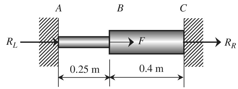
Use the finite element method to determine the axial force P in each portion, AB and BC, of the uniaxial bar. What are the support reactions? Assume:
Want to see the full answer?
Check out a sample textbook solution
Chapter 1 Solutions
Introduction To Finite Element Analysis And Design
Additional Engineering Textbook Solutions
Engineering Mechanics: Statics & Dynamics (14th Edition)
Engineering Mechanics: Statics
Applied Statics and Strength of Materials (6th Edition)
Manufacturing Engineering & Technology
Engineering Mechanics: Dynamics (14th Edition)
Automotive Technology: Principles, Diagnosis, and Service (5th Edition)


- NOTE: This is a multi-part question. Once an answer is submitted, you will be unable to return to this part. The 6-m long pole ABC is acted upon by a 495-N force as shown in the figure. The pole is held by a ball-and-socket joint at A and by two cables BD and BE. 1.5 m> P E C B 3 m N. N)i + ( 3 m 3 m 1.5 m D 3 m For a = 1.5 m, determine the tension in each cable and the reaction at A. The tension in cable BD is N. The tension in cable BE is The reaction at A is - ([ N)j + ( N)k.arrow_forwardThe pipe shown below is held in place by a support at A, and a cable as shown. The support at A is fixed in all directions, except that it is free to translate along the y axis. Force F = 13î + 28ĵ – 2k N is acting at point E. Find the reactions at A 18 mm G 30 mm 6 mm 15 mm 8 mm 10 mmarrow_forwardThe armor shown supports loads of 3 KN. The horizontal elements are 713cm long each. Determine the axial force on element FE; Use the section method to determine the axial force in the FE element and check your result with the nodal or joint method. INFO: Y= 100 cmarrow_forward
- A rigid beam is supported by a pin at A and two metallic wires at B and C. Determine the force P that causes the point C to displace downward by 0.1 mm. Given: E (wire B) = 200 Gpa, E (wire C)70 Gpa and both wires have a diameterD =6 mm. Consider a linear elastic behavior.A rigid beam is supported by a pin at A and two metallic wires at B and C. Determine the force P that causes the point C to displace downward by 0.1 mm. Given: E (wire B) = 200 Gpa, E (wire C)70 Gpa and both wires have a diameterD =6 mm. Consider a linear elastic behavior.arrow_forwardA rigid beam is supported by a pin at A and two metallic wires at B and C. Determine the force P that causes the point C to displace downward by 0.6 mm. Given: E (wire B) = 200 Gpa, E (wire C) = 70 Gpa and both wires have a diameter D = 2 mm. Consider a linear elastic behavior. 2 m 1.5 m C 3 m 2 m 2 m Select one: O P= 235 N O P= 471 N O P= 314 N P= 294 Narrow_forwardA rectangular steel block is 4 inches long in the x-direction, 6 inches long in the y-direction, and 3 inches long in the z-direction. The block is subjected to a tri-axial loading of three uniform distributed forces as follows: 55 kips compression in the x direction, 62 kips tension in the y direction, and 24 kips tension in the z direction. If the Poisson’s ration is 0.26 and E = 29 x 106 psi, determine the single uniform distributed load in the y direction that would produce the same deformation in the x direction as the original loading.arrow_forward
- 3. The rigid bar AB is supported by two rods made of the same material. If the bar is horizontal before the load P is applied, find the distance x that locates the position where P must act if the bar is to remain horizontal. Neglect the weight of bar AB. L = 3 ft A = 0.2 in.2 L = 2 ft A = 0.4 in.2 х X B 10 ftarrow_forwardA light ridig member AB is pinned at A and is further supported by light elastic rods CD and GF, member AB supports a 5000lb load at B the elastic modulus for the two elastic rods CD and GF is given as E= 30x106 psi and the cross-sectional area for each of these rods is 1 in2. what are the forces in the two supporting elastic rods as a results of the loading?arrow_forwardA rigid beam is supported by a pin at A and two metallic wires at B and C. Determine the force P that causes the point C to displace downward by 0.3 mm. Given: E (wire B) = 200 Gpa, E (wire C) = 70 Gpa and both wires have a diameter D = 4 mm. Consider a linear elastic behavior. 2 m 1.5 m A B 3 m 2 m 2 m Select one: P = 157 N P = 314 N P = 235 N P = 294 N P = 471 N Karrow_forward
- A rectangular steel block is 3 inches long in the x direction, 2 inches long in the y direction, and 4 inches long in the z direction. The block is subjected to a triaxial loading of three uniformly distributed forces as floows; 48 kips tension in the x directio, 60 kips compression in the y direction, and 54 kips tension in the z direction. If v = 0.30 and E = 29 x 106 psi, determine the single uniformly distributed load in the x direction that would produce the same deformation in the y direction as the original loading.arrow_forwardA rigid beam is supported by a pin at A and two metallic wires at B and C. Determine the force P that causes the point C to displace downward by 0.6 mm. Given: E (wire B) = 200 Gpa, E (wire C) = 70 Gpa and both wires have a diameter D = 2 mm. Consider a linear elastic behavior.arrow_forwardThe uniform 44 kN bar BC is supported by a pin at C and the aluminum wire AB. The cross-sectional area of the wire is 178.5 mm2. Assuming bar BC to be rigid, find the vertical displacement of B due to the weight of the bar. Use E = 71 GPa for aluminum. Anwer must be in mm.arrow_forward
 Elements Of ElectromagneticsMechanical EngineeringISBN:9780190698614Author:Sadiku, Matthew N. O.Publisher:Oxford University Press
 Mechanics of Materials (10th Edition)Mechanical EngineeringISBN:9780134319650Author:Russell C. HibbelerPublisher:PEARSON
 Thermodynamics: An Engineering ApproachMechanical EngineeringISBN:9781259822674Author:Yunus A. Cengel Dr., Michael A. BolesPublisher:McGraw-Hill Education
 Control Systems EngineeringMechanical EngineeringISBN:9781118170519Author:Norman S. NisePublisher:WILEY
 Mechanics of Materials (MindTap Course List)Mechanical EngineeringISBN:9781337093347Author:Barry J. Goodno, James M. GerePublisher:Cengage Learning
 Engineering Mechanics: StaticsMechanical EngineeringISBN:9781118807330Author:James L. Meriam, L. G. Kraige, J. N. BoltonPublisher:WILEY