
Videos
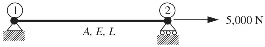
The uniaxial bar shown below can be modeled as a one-dimensional bar. The bar has the following properties:
a. Calculate the global matrix equation after applying boundary conditions.
b. Solve for the displacement
c. What is the element force P in the bar?
Want to see the full answer?
Check out a sample textbook solution
Chapter 1 Solutions
Introduction To Finite Element Analysis And Design
Additional Engineering Textbook Solutions
Starting Out with Programming Logic and Design (5th Edition) (What's New in Computer Science)
Java How to Program, Early Objects (11th Edition) (Deitel: How to Program)
Starting Out With Visual Basic (8th Edition)
Starting Out with Java: From Control Structures through Objects (7th Edition) (What's New in Computer Science)
Modern Database Management
Java: An Introduction to Problem Solving and Programming (8th Edition)


- The hose supplying the cylinder operating the bucket of a large excavator has fluid at 1000 psi flowing at 5 gpm. What is theavailable power in the line?arrow_forwardQ For the following plan of building foundation, Determine immediate settlement at points (A) and (B) knowing that: E,-25MPa, u=0.3, Depth of foundation (D) =1m, Depth of layer below base level of foundation (H)=10m. 3m 2m 100kPa A 2m 150kPa 5m 200kPa Barrow_forwardGiven the following data for crack rocker mechanism. If θ2 = 4π/3 and ω2 = 1 rad/s, Determine all possible values of ω4 and ω3 analytically. The lengths of links are a = 2, b = 8, c = 7 and d = 9 in cm.arrow_forward
- Q6] (20 Marks) Select the most suitable choice for the following statements: modo digi -1A 10 af5 1 -The copper-based alloy which is responded to age hardening is a) copper-nickel b) aluminum bronze c) copper - beryllium d) brass besincaluy 2- Highly elastic polymers may experience elongations to greater than.... b) 500% bromsia-P c) 1000%. d) 1200% 15m or -2 a)100% 3- The cooling rate of quenching the steel in saltwater will be ......the cooling rate of quenching ir c) faster than sold) none of them a) slower than 4- Adding of a) Cr b) the same as ...... Will lead to stabilize the b) Mo 10 austenite in steel. c) Nimble avolls 1d) Sized loloin nl 5- The adjacent linear chains of crosslinked polymers are joined one to another at various positic DIR... by.........bonds c) covalent noisqo gd) ionic lg 120M 6- For the ceramic with coordination number 6 the cation to anion radius ratio will be a) Van der Waals a) 0.155-0.225 a) linear b) hydrogen (b) 0.225-0.414 c) 0.414 0.732 ..polymers.…arrow_forwardExamine Notes: Attempt Six Questions Only. rever necessa , Q1] (20 Marks) Answer with true (T) or false (F), corrects the wrong phrases, and gives sho reasons for correct and corrected statements: 1- High chromium irons are basically grey cast irons alloyed with 12 to 30 % Cr. yous board-19qgo orT-1 2- The drawbacks of Al- Li alloys are their high young modulus and high density.&M 0) (0 3- Vulcanized rubbers are classified under thermoplastic polymers. 4- Diamond is a stable carbon polymorph at room temperature and atmospheric pressure. ( 5- The metallic ions of ceramic are called anions, and they are positively charged. yldgiH-S 69001(6arrow_forwardH.W 5.4 Calculate the load that will make point A move to the left by 6mm, E-228GPa. The diameters of the rods are as shown in fig. below. 2P- PA 50mm B 200mm 2P 0.9m 1.3marrow_forward
- d₁ = = Two solid cylindrical road AB and BC are welded together at B and loaded as shown. Knowing that 30mm (for AB) and d₂ 50mm (for BC), find the average normal stress in each road and the total deformation of road AB and BC. E=220GPa H.W 5.3 60kN A For the previous example calculate the value of force P so that the point A will not move, and what is the total length of road AB at that force? P◄ A 125kN 125kN 0.9m 125kN 125kN 0.9m B B 1.3m 1.3marrow_forwardClass: B Calculate the load that will make point A move to the left by 6mm, E-228GPa The cross sections of the rods are as shown in fig. below. 183 P- Solution 1.418mm 200mm 80mm 3P- 18.3 A 080mm B 200mm 3P- 0.9m إعدادات العرض 1.3m 4.061mmarrow_forwardH.W6 Determine the largest weight W that can be supported by two wires shown in Fig. P109. The stress in either wire is not to exceed 30 ksi. The cross- sectional areas of wires AB and AC are 0.4 in2 and 0.5 in2, respectively. 50° 30° Warrow_forward
- Find equation of motion and natural frequency for the system shown in fig. by energy method. H.W2// For the system Fig below find 1-F.B.D 2-Eq.of motion 8wn 4-0 (5) m. Jo marrow_forward2. Read the following Vernier caliper measurements. (The scales have been enlarged for easier reading.) The Vernier caliper is calibrated in metric units. (a) 0 1 2 3 4 5 سلسلسله (b) 1 2 3 4 5 6 سلسل (c) 1 23456 (d) 1 2 3 4 5 6 سلسلسarrow_forwardExplain why on the interval 0<x<1000 mm and 1000<x<2000mm, Mt is equal to positive 160 Nm, but at x= 0mm and x=1000mm Mt is equal to -160 Nm (negative value!). What is the reason for the sign change of Mt?arrow_forward
 Mechanics of Materials (MindTap Course List)Mechanical EngineeringISBN:9781337093347Author:Barry J. Goodno, James M. GerePublisher:Cengage Learning
 Principles of Heat Transfer (Activate Learning wi...Mechanical EngineeringISBN:9781305387102Author:Kreith, Frank; Manglik, Raj M.Publisher:Cengage Learning