
Videos
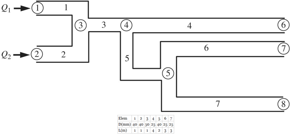
The finite element equation for the uniaxial bar can be used for other types of engineering problems if a proper analogy is applied. For example, consider the piping network shown in the figure. Each section of the network can be modeled using an FE. If the flow is laminar and steady, we can write the equations for a single pipe element as:
a. Write the element matrix equation for the flow in the pipe element.
b. The net flow rates into nodes 1 and 2 are 10 and 15 m3/s, respectively. The pressures at the nodes 6, 7, and 8 are all zero. The net flow rate into the nodes 3, 4, and 5 are all zero. What is the outflow rate for elements 4, 6, and 7?
Want to see the full answer?
Check out a sample textbook solution
Chapter 1 Solutions
Introduction To Finite Element Analysis And Design
Additional Engineering Textbook Solutions
Mechanics of Materials (10th Edition)
Engineering Mechanics: Dynamics (14th Edition)
Statics and Mechanics of Materials (5th Edition)
Automotive Technology: Principles, Diagnosis, and Service (5th Edition)
Thinking Like an Engineer: An Active Learning Approach (3rd Edition)
Engineering Mechanics: Statics & Dynamics (14th Edition)


- du Water flows past a flat plate that has a length L = 5 m and a width w = 2 m, as shown in Figure Q4. The shear stress at the wall is given by Tw = μ When the flow is laminar the shear stress at the wall is given by the equation: 8 Tw = 0.0644 pU² Where p = 1000 kg/m³ is the water density and U = 5 m/s is the velocity of the water. The height of the boundary layer is 8, and can be approximated by 8(x) = 5 The viscosity of water is μ = 1 mPa.s. a) Estimate the drag force on the plate. You may use the expression FD = S TwdA μx puco b) When the flow becomes turbulent, we can approximate the velocity gradient at the wall as constant, du = A. If the total drag force is 300 N, find A. ?u U c) When the fluid is heated to 90°C, the density drops slightly and the viscosity decreases a lot, and engineers observe that the equation, Tw= 0.0644pU² - becomes less accurate. Explain why this might occur (1-2 sentences). d) In order to visually examine a turbulent boundary layer, engineers release a…arrow_forwardAn infinitely long cylindrical container has a cross section area of radius R, and is placed horizontally with gravity being in the −y direction, as shown in the figure. The cylinder is 50% filled with water (the shaded part), with density ρ. The other 50% of the volume in the cylinder is filled with air with constant pressure of p = p0. The length of the cylindrical container in the axial direction is W. c) Use control volume analysis and divergence theorem on the 4th quadrant water volume to compute the hydrostatic force acted on the 4th quadrant of the cylinder wall, as shown by the thickened line in the figure.arrow_forwardQ. No. 1: (a) Determine the possible flows in the network shown in Figure below. And solve a system of linear equations to find the possible flows. X7 В x1 TA 150 > A D 300 E X2 Q. No. 1: (b) The metal plate has the constant temperature shown on its boundaries. Find the equilibrium temperature at each of the indicated interior points by setting up a system of linear equations and obtain a solution by applying either the Gauss elimination or the Gauss Jordan elimination method. 40° 0° 40° t2 13 0° 40° 14 t5 t6 0° 40° 5° 5° 5°arrow_forward
- Question 4 du Water flows past a flat plate that has a length L = 5 m and a width w = 2 m, as shown in Figure Q4. The shear stress at the wall is given by Tw = μ- When the flow is laminar the shear stress at the wall is given by the equation: dy Tw = 0.0644 PU² The viscosity of water is μ = 1 mPa.s. 8(x) = 5 - Where p = 1000 kg/m³ is the water density and U.. = 5 m/s is the velocity of the water. The height of the boundary layer is 8, and can be approximated by μx puo X 1arrow_forwardWater flows past a flat plate that has a length L = 5 m and a width w = 2 m, as shown in Figure Q4. The shear stress at the wall is given by Tw= μ du dy. When the flow is laminar the shear stress at the wall is given by the equation: Tw = 0.0644 pU 2 8 x Where p = 1000 kg/m3 is the water density and U∞ = 5 m/s is the velocity of the water. The height of the boundary layer is 5, and can be approximated by 8(x) = 5√ ux pU* The viscosity of water is μ = 1 mPa.s. a) Estimate the drag force on the plate. You may use the expression FD = | TwdA b) When the flow becomes turbulent, we can approximate the velocity gradient at the wall as constant, au ay = A. If the total drag force is 300 N, find A. c) When the fluid is heated to 900C, the density drops slightly and the viscosity decreases a lot, and engineers observe that the equation, Tw = 0.0644pU 2 6 x, becomes less accurate. Explain why this might occur (1-2 sentences). d) In order to visually examine a turbulent boundary layer, engineers…arrow_forwardWater (at 20C) flows through a pipeline connected in series, as shown in the Figure. The construction material of the pipes is commercial steel. Diameters of the first and second pipe are 1¼ inch nominal (42.4/3.25 mm) and ¾ inch nominal(26.9/2.65 mm), respectively. No elevation difference exits in the system. If the pressures at point A and at point B are 12.63 mWH absolute and 10.33 mWH absolute, respectively, what is the volumetric flow rate in the pipeline? Neglect the contraction losses in the connection of two pipes.Note: Friction factor must be found from MOODY DIAGRAM. For simplification in the reading of Moody diagram, take relative roughness of each pipe as: E/D1=0.001 and E/D2=0.002Figure Q2.1. Schematic illustration of the series-connected pipeline system.Figure Q2.2. Moody diagramarrow_forward
- Consider a Newtonian fluid between two fixed wide, parallel plates, shown in the figure below, the velocity distribution for the fluid flow is given by: 3V u = 2 where V is the mean velocity. The fluid has a viscosity of 19.1 Poise, Also V = 0.6 m/s and h = 0.5 cm. Determine: a. The shear stress acting on the bottom wall. (30 points) b. The shear stress acting on a plane parallel to the walls and passing through the centerline between the two plates. (30 points) c. Plot the shear stress variation versus the y direction. (15 рoints) d. Repeat part (b) if the velocity is linear between the two plates and for the same value of V = 0.6 m/s at the centerline. Interpret your result. (15 points) e. Explain the differences between Newtonian and Non-Newtonian fluid. (10 points)arrow_forward1. Find the flow distribution in the three-parallel pipe system shown in figure below. Take Qin = 2500 L/min. Element L, m D, mm fo EK lin 1 50 75 0.02 2 2 80 85 0.03 4 3 3 120 100 0.025 2 Ans: Q₁ = 731 L/min, Q₂ = 790 L/min, Q₂ = 979 L/min * Marrow_forward4. For a parallel plate arrangement of the type shown in Figure Q4, it is found that when the distance between plates is 2 mm, a shearing stress of 150 Pa develops at the upper plate when it is pulled at a velocity of 1 m/s. Assume the velocity distribution is linear between the plates, Determine: (i) the dynamic viscosity of the fluid between the plates. (2 marks) (a)0.3 N.S/m² (b) 3.3 N.S/m² (c) 0.3 kg S/m² 'arrow_forward
- Three pipes A, B, and C are interconnected as shown in figure 1. The pipe dimensions are as follows: Pipeline D(cm) L (m) ƒA 15 300 0.01B 10 240 0.01C 20 600 0.005 Find the pressure at P?arrow_forward3-Given Cast-iron pipe (e - 0.25 mw), (L=120w), ChL=S) こ (u=10 m/s.) ofwater (D=10 m) find: -Discharge. b- shear stress at the pipe wall-arrow_forwarddu Water flows past a flat plate that has a length L = 5 m and a width w = 2 m, as shown in Figure Q4. The shear stress at the wall is given by tw = When the flow is laminar the shear stress at the wall is given by the equation: Tw = 0.0644 pU²- Where p = 1000 kg/m³ is the water density and U∞ = 5 m/s is the velocity of the water. The height of the boundary layer is 8, and can be approximated by 8(x) = 5 μx puco The viscosity of water is μ = 1 mPa.s. a) Estimate the drag force on the plate. You may use the expression FD = S TwdA b) When the flow becomes turbulent, we can approximate the velocity gradient at the wall as constant, A. If the total drag force is 300 N, find A. du ду c) When the fluid is heated to 90°C, the density drops slightly and the viscosity decreases a lot, and engineers observe that the equation, tw = 0.0644pU² becomes less accurate. Explain why this might occur (1-2 sentences). U d) In order to visually examine a turbulent boundary layer, engineers release a steady…arrow_forward
 Elements Of ElectromagneticsMechanical EngineeringISBN:9780190698614Author:Sadiku, Matthew N. O.Publisher:Oxford University Press
 Mechanics of Materials (10th Edition)Mechanical EngineeringISBN:9780134319650Author:Russell C. HibbelerPublisher:PEARSON
 Thermodynamics: An Engineering ApproachMechanical EngineeringISBN:9781259822674Author:Yunus A. Cengel Dr., Michael A. BolesPublisher:McGraw-Hill Education
 Control Systems EngineeringMechanical EngineeringISBN:9781118170519Author:Norman S. NisePublisher:WILEY
 Mechanics of Materials (MindTap Course List)Mechanical EngineeringISBN:9781337093347Author:Barry J. Goodno, James M. GerePublisher:Cengage Learning
 Engineering Mechanics: StaticsMechanical EngineeringISBN:9781118807330Author:James L. Meriam, L. G. Kraige, J. N. BoltonPublisher:WILEY