
Concept explainers
Videos
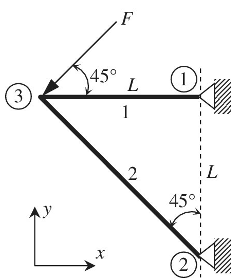
The plane truss shown in the figure has two elements and three nodes. Calculate the
Want to see the full answer?
Check out a sample textbook solution
Chapter 1 Solutions
Introduction To Finite Element Analysis And Design
Additional Engineering Textbook Solutions
Applied Statics and Strength of Materials (6th Edition)
Introduction to Heat Transfer
Automotive Technology: Principles, Diagnosis, And Service (6th Edition) (halderman Automotive Series)
Statics and Mechanics of Materials (5th Edition)
Automotive Technology: Principles, Diagnosis, and Service (5th Edition)
Engineering Mechanics: Statics & Dynamics (14th Edition)


- A large precast concrete panel for a warehouse is raised using two sets of cables at two lift lines, as shown in the figure part a. Cable 1 has a length L1 = 22 Ft, cable 2 has a length L2= 10 ft, and the distance along the panel between lift points Band D is d = 14 ft (see figure part b). The total weight of the panel is W = 85 kips. Assuming the cable lift Forces F at each lift line are about equal, use the simplified model of one half of the panel in figure part b to perform your analysis for the lift position shown. Find the required cross-sectional area AC of the cable if its breaking stress is 91 ksi and a factor of safety of 4 with respect to failure is desired.arrow_forward1.3-15 A space truss is restrained at joints A, B, and C, as shown in the figure. Load 2P is applied at in the -x direction at joint A, load 3P acts in the + - direction at joint B. and load P is applied in the + r direction al joint C. Coordinates of all joints are given in terms of dimension variable L (see figure). (a) Find reaction force components Ayand Azin terms of load variable P. (b) Find the axial force in truss member AB in terms of load variable P.arrow_forwardRepeat 1.3-9 but use the method of sections go find member forces in AC and BD.arrow_forward
- A cable and pulley system in the figure part a supports a cage of a mass 300 kg at B. Assume that this includes the mass of the cables as well. The thickness or each of the three steel pulleys is t = 40 mm. The pin diameters are dPA= 25 mm, dB= 30 mm. and dc= 22 mm (see figure part a and part b). (a) Find expressions for the resultant forces acting on the pulleys at A, B. and C in terms of cubic tension T. (b) What is the maximum weight W that can be added to the cage at B based on the following allowable stresses? Shear stress in the pins is 50 MPa; bearing stress between the pin and the pulley is 110 MPa.arrow_forwardIn the figure, the horizontal rigid beam ABCD is supported by vertical bars (1) and (2) and is loaded at points A and D by vertical forces P = 28 kN and Q = 40 kN, respectively. Bar (1) is made of aluminum [E = 70 GPa] and has a cross-sectional area of 210 mm² and a length of L₁ = 7.3 m. Bar (2) is made of steel [E = 200 GPa] and has a cross-sectional area of 355 mm² and a length of L₂ = 5.2 m. Assume dimensions a = 3.6 m, b = 2.6 m, and c = 2.2 m. Determine the deflection of the rigid beam (a) at point A and (b) at point D. (a) VA = (b) VD = i tel L₁ mm mm B (1) b L₂ 3,V C (2) X₂U Darrow_forwardRAX M A 0 F RAY Enter FAP: kN F₂ The figure above is a pin-joint frame with angle = 30° between members AF and AB. (Note that the diagram is not to scale). Given that the reaction forces at the support A are given by RAX = 10kN and RAY = 25kN, calculate the forces in members AB and AF, denoted by FAB and FAP respectively. Enter your answers in kilonewtons (kN) correct to 2 decimal places in the boxes below: Enter FAB KN D RDYarrow_forward
- The figure below shows a cable supporting a beam. In addition there is a vertical force acting on the right end of the beam. L Calculate the normal force N(x), the shear force V (x), the moment M(x) as a function of the parameters L and f. (Partial Answer: N(x) = 2f for 0arrow_forwardFigure 6: 5 m/ 5 m A 5 m B 20 KN A simple truss is subjected to 20 KN force at the point A as shown in Figure 6. The reaction force at point C is (in kN): (a) 20 Compression (b) 20 Tension (c) 30 Compression (d) 30 Tensionarrow_forwardThe beam shown in Figure Q.2 consists of a W610 x 140 structural steel wide-flange shape [E = 200 GPa; /= 1120 x 106 mm4]. If w=65 kN/m and P= 124 kN, determine: A AV, V 1.5 m B W 3.5 m P 2.5 m D Figure Q.2 Part A: The reactions at A, B, and D. Choose the reaction force at B as the redundant; therefore, the released beam is simply supported between A and D. a) Calculate the value of the deflection at point B due to uniformly distributed load win the form UB = numerator EI Note: E/will cancel out in further calculations. Enter the numerator in the answer box below in kNm³ to three decimal places. Assume the positive direction of deflection in the positive direction of v axis.arrow_forwardFind the Tensions TCA and TCB for the system as shown in figure. Take R = 200 mm, S= 240 mm 0 = 55°, W= 14 kN ( Solve the problem in a paper and upload the file in a separate link provided. Also enter only the values in the boxes below. ) Tension TCA in N is Tension TCB in N isarrow_forwardPart of a two story building is shown in the figure in which a concerte column and a steel column are used in the first and second floor. The compressive force on the roof of the second floor is PC = 370 kN. The compressive force on the first floor is PB = 420 kN. The steel [Esteel = 200 GPa] column is a wide angle steel shape that has a cross section area of A2 = 1950 mm2. The concrete [Econcrete = 30 GPa] column has a circular section with a diameter of d = 560 mm.[L1 = 5.6 m, L2 = 5.6 m] Using this equation FL/AEarrow_forwardIn the train bridge in the figure, select the F1 and F2 forces from 107 to 207 kN with a non- zero end. Find the force on the bar BC and whether it is the pull. ? (Note: Fill in the table.) F1= 125 kN F2= 165 kN a) BC = ? [kN] b) compression or в tension? F1 KN F2 KN to 10 m 10m 10 m 10 marrow_forwardarrow_back_iosSEE MORE QUESTIONSarrow_forward_ios
 Mechanics of Materials (MindTap Course List)Mechanical EngineeringISBN:9781337093347Author:Barry J. Goodno, James M. GerePublisher:Cengage Learning