
Introduction To Finite Element Analysis And Design
2nd Edition
ISBN: 9781119078722
Author: Kim, Nam H., Sankar, Bhavani V., KUMAR, Ashok V., Author.
Publisher: John Wiley & Sons,
expand_more
expand_more
format_list_bulleted
Concept explainers
Videos
Textbook Question
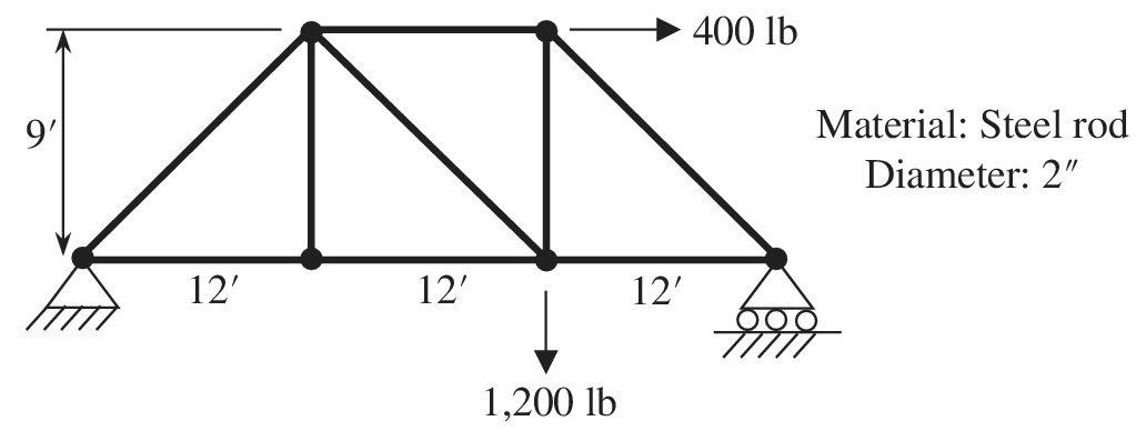
Chapter 1, Problem 34E
Determine the member force and axial stress in each member of the truss shown in the figure using a commercial finite element analysis program. Assume that Young’s modulus is psi and all cross sections are circular with a diameter of 2 in. Compare the results with the exact solutions that are obtained from the free-body diagram.
Expert Solution & Answer
Want to see the full answer?
Check out a sample textbook solution
Students have asked these similar questions
Problem 1
Calculate the displacements at nodes 1 and 2, the reactions at nodes 1 and 3, as well as the
axial strains and stresses in the three bars of the planar truss shown below. Use analytical (hand)
finite element formulation. Known are P₁ = 500 N, P₂= 1000 N. /= 0.05 m, the constant cross-
sectional area of all bars A = 0.0001 m², Young's modulus E= 2 x 10¹¹ N/m², and Poisson's ratio
v=0.3.
V
P₂
R
21
Problem 2
Remove the loads in Problem 1 and calculate the natural frequencies of the truss for a mass
density p= 7800 kg/m³ using analytical calculation.
A rectangular piece of wood, 50 mm x 100 mm in cross-section is used as acompression block as shown in the figure. Determine the maximum axial load P whichcan be safely applied to the block if the compressive stress in the wood is limited to 20MPa.
The bars of the truss, shown in the Figure, are made of
aluminium (yield strength-410 MPa), each with a cross-
sectional area of 30 mm². After applying the shown forces,
members EC and ED failed to support the applied loads. Do the
following:
5 m
MUN
3.5 m
BO
5 m
5 kN
9 kN
25%
DE
5 m
a)Calculate the normal stress in members EC and
ED and indicate whether these members are in tension or
compression.
b) As a potential solution, determine which member,
EC or ED, should be reinforced to prevent failure. Provide
a justification for your choice.
Chapter 1 Solutions
Introduction To Finite Element Analysis And Design
Ch. 1 - Answer the following descriptive questions a....Ch. 1 - Calculate the displacement at node 2 and reaction...Ch. 1 - Repeat problem 2 by changing node numbers; that...Ch. 1 - Three rigid bodies, 2,3, and 4, are connected by...Ch. 1 - Three rigid bodies, 2,3, and 4, are connected by...Ch. 1 - Consider the spring-rigid body system described in...Ch. 1 - Four rigid bodies, 1, 2, 3, and 4, are connected...Ch. 1 - Determine the nodal displacements, element forces,...Ch. 1 - In the structure shown, rigid blocks are connected...Ch. 1 - The spring-mass system shown in the figure is in...
Ch. 1 - A structure is composed of two one-dimensional bar...Ch. 1 - Two rigid masses, 1 and 2, are connected by three...Ch. 1 - Use the finite element method to determine the...Ch. 1 - Consider a tapered bar of circular cross section....Ch. 1 - The stepped bar shown in the figure is subjected...Ch. 1 - Using the direct stiffness matrix method, find the...Ch. 1 - A stepped bar is clamped at one end and subjected...Ch. 1 - A stepped bar is clamped at both ends. A force of ...Ch. 1 - Repeat problem 18 for the stepped bar shown in the...Ch. 1 - The finite element equation for the uniaxial bar...Ch. 1 - The truss structure shown in the figure supports a...Ch. 1 - The properties of the two elements of a plane...Ch. 1 - For a two-dimensional truss structure as shown in...Ch. 1 - The 2D truss shown in the figure is assembled to...Ch. 1 - For a two-dimensional truss structure as shown in...Ch. 1 - The truss shown in the figure supports force Fat...Ch. 1 - Prob. 27ECh. 1 - In the finite element model of a plane truss in...Ch. 1 - Use the finite element method to solve the plane...Ch. 1 - The plane truss shown in the figure has two...Ch. 1 - Two bars are connected as shown in the figure....Ch. 1 - The truss structure shown in the figure supports...Ch. 1 - It is desired to use the finite element method to...Ch. 1 - Determine the member force and axial stress in...Ch. 1 - Determine the normal stress in each member of the...Ch. 1 - The space truss shown has four members. Determine...Ch. 1 - The uniaxial bar shown below can be modeled as a...Ch. 1 - In the structure shown below, the temperature of...Ch. 1 - Prob. 39ECh. 1 - The three-bar truss problem in figure 1.23 is...Ch. 1 - Use the finite element method to determine the...Ch. 1 - Repeat problem 41 for the new configuration with...Ch. 1 - Repeat problem 42 with an external force added to...Ch. 1 - The properties of the members of the truss in the...Ch. 1 - Repeat problem 44 for the truss on the right side...Ch. 1 - The truss shown in the figure supports the force ....Ch. 1 - The finite element method as used to solve the...Ch. 1 - Prob. 48E
Additional Engineering Textbook Solutions
Find more solutions based on key concepts
What is the moment of this force about point B. Specify the coordinate direction angles , , of the moment axis...
INTERNATIONAL EDITION---Engineering Mechanics: Statics, 14th edition (SI unit)
Determine the resultant internal normal force, shear force, and bending moment at point C in the beam.
Mechanics of Materials (10th Edition)
Modified coefficient of performance and power input for clean condition.
Introduction to Heat Transfer
A gas-powered cannon shoots projectiles by introducing nitrogen gas at 20.5 MPa into a cylinder having an insid...
Applied Fluid Mechanics (7th Edition)
A piece of experimental apparatus. Fig. P1.54. is located where g=9.5m/s2 and the temperature is 5C . Air flow ...
Fundamentals Of Thermodynamics
1.1 What is the difference between an atom and a molecule? A molecule and a crystal?
Manufacturing Engineering & Technology
Knowledge Booster


Learn more about
Need a deep-dive on the concept behind this application? Look no further. Learn more about this topic, mechanical-engineering and related others by exploring similar questions and additional content below.Similar questions
- A steel riser pipe hangs from a drill rig located offshore in deep water (see figure). (a) What is the greatest length (meters) it can have without breaking if the pipe is suspended in the air and the ultimate strength (or breaking strength) is 550 MPa? (b) If the same riser pipe hangs from a drill rig at sea, what is the greatest length? (Obtain the weight densities of steel and sea water from Table M, Appendix I. Neglect the effect of buoyant foam casings on the pipe.)arrow_forwardTruss members supporting a roof are connected to a 26-mm-thick gusset plate by a 22-mm diameter pin, as shown in the figure and photo. The two end plates on the truss members are each 14 mm thick. (a) If the load P = 80 kN, what is the largest bearing stress acting on the pin? (b) If the ultimate shear stress for the pin is 190 MPa, what force Pult is required to cause the pin to fail in shear? Disregard friction between the plates.arrow_forwardDuring a tension lest of a mild-steel specimen (see figure), the extensometer shows an elongation of 0.00120 in. with a gage length of 2 in. Assume that the steel is stressed below the proportional limit and that the modulus of elasticity E = 30 × 10 psi. (a) What is the maximum normal stress (j^, in the specimen? (b) What is the maximum shear stress tmax? (c) Draw a stress element oriented at an angle of 45° to the axis of the bar, and show all stresses acting on the faces of this element.arrow_forward
- A long re Lai nine: wall is braced by wood shores set at an angle of 30° and supported by concrete thrust blocks, as shown in the first part of the figure. The shores are evenly spaced at 3 m apart. For analysis purposes, the wall and shores are idealized as shown in the second part of the figure. Note that the base of the wall and both ends of the shores are assumed to be pinned. The pressure of the soil against the wall is assumed to be triangularly distributed, and the resultant force acting on a 3-meter length of the walls is F = 190 kN. If each shore has a 150 mm X 150 mm square cross section, what is the compressive stressarrow_forwardA spherical balloon is filled with a gas. The outer diameter of the balloon is 20 in. and the thickness is 0,012 in. Calculate the maximum permissible pressure in the balloon if the allowable tensile stress and the allowable shear stress in the balloon are 1 ksi and 0.3 ksi, respectively.arrow_forwardA sign of weight W is supported at its base by four bolls anchored in a concrete footing. Wind pressure P acts normal to the surface of the sign; the resultant of the uniform wind pressure is force fat the center of pressure (C.P). The wind force is assumed to create equal shear forces F/4 in the y direction at each boll (see figure parts a and c). The overturning effect of the wind force also causes an uplift force R at bolts A and C and a downward force (— R) al bolts B and D (see figure part b). The resulting effects of the wind and the associated ultimate stresses for each stress condition are normal stress in each boll (h — 60 ksi); shear through the base plate (th = 17 ksi); horizontal shear and bearing on each bolt ( tfur = 25 ksi and cr^ = 75 ksi): and bearing on the bottom washer at B (or D) (abor = 50 ksi).arrow_forward
- An aluminum bar subjected to tensile Forces P has a length L = 150 in. and cross-sectional area A = 2.0 in2 The stress-strain behavior of the aluminum may be represented approximately by the bilinear stress-strain diagram shown in the figure. Calculate the elongation S of the bar for each of the following axial loads: p = 8 kips, 16 kips. 24 kips, 32 kips, and 40 kips. From these results, plot a diagram of load P versus elongation S (load-displacement diagram).arrow_forwardQ1/ The aluminum bar has been subjected to axial loads at the positions shown in Figure below. Calculate the internal stresses at section (A-B), (B-C) and (C-D), and the elongation (AL) in length at each part of aluminum due to loading, if the diameter for part AB, BC and CD is 28 mm, 46 mm and 34 mm, respectively. The elastic modulus for aluminum is 74.4 x 10 N/mm. A B D 33 kN 17 kN 29 kN 14 kN 940 mm 860 mm 550 mmarrow_forwardPlease help me understand this solution. I want to know how the stress in concrete was solved for. I don't quite understand beyond part ii). Attached is the problem and the solution This is the problem: The figure shows the cross section of a circular steel tube that is filled with concrete and topped with a rigid cap. Calculate the stresses in the steel and in the concrete caused by the 200-kip axial load. Use Est = 29 x 106 psi and Eco = 3.5 x 10⁶ psi.arrow_forward
- The figure shows the cross section of a steel tube that is filled with concrete and topped with a rigid cap. Calculate the stresses in the steel and in the concrete caused by the 200-kip axial load. Use Est=29x10^6 psi and Eco=3.5x10^6 psi. -Draw and label the diagram correctly, No diagram in the solution will be marked wrong. -Shortcut solution will be marked wrong.- Direction of the assumption of the equilibrium equation must be shown, no direction will be marked wrong.arrow_forwardSIMPLE STRESS For the structure shown in the figure, the working stresses are up to 16000 psi for the steel cable AB and 720 psi for the wood strut BC. (a) Which of the two members, namely AB and BC, is at maximum allowable stress when W is largest? Justify your answer with supporting calculations (b) iF W is 7000 lbs, find the stress in each member. Specify if tensile or compressive stress. SHOW FBD.arrow_forwardA rod of weight 800kg is supported at the end using Steel and Bronze cable as shown in the figure below. The maximum allowable stress for Steel and bronze is 120 MPa and 90 MPa respectively. Calculate the diameter of each cable. Tbronze Tsteel 5 m 5 m Wrodarrow_forward
arrow_back_ios
SEE MORE QUESTIONS
arrow_forward_ios
Recommended textbooks for you
 Mechanics of Materials (MindTap Course List)Mechanical EngineeringISBN:9781337093347Author:Barry J. Goodno, James M. GerePublisher:Cengage Learning
Mechanics of Materials (MindTap Course List)
Mechanical Engineering
ISBN:9781337093347
Author:Barry J. Goodno, James M. Gere
Publisher:Cengage Learning
Pressure Vessels Introduction; Author: Engineering and Design Solutions;https://www.youtube.com/watch?v=Z1J97IpFc2k;License: Standard youtube license