
Concept explainers
Videos
In the structure shown below, the temperature of element 2 is 50°C above the reference temperature. An external force of 20.000 N is applied in the x direction (horizontal direction) at node 2. Assume
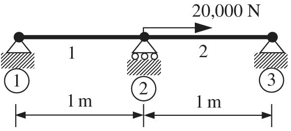
a. Write down the stiffness matrices and thermal force
b. Write down the global matrix equations.
c. Solve the global equations to determine the displacement at node 2.
d. Determine the forces in each element. State whether it is tension or compression.
e. Show that force equilibrium is satisfied at node 2.
Want to see the full answer?
Check out a sample textbook solution
Chapter 1 Solutions
Introduction To Finite Element Analysis And Design
Additional Engineering Textbook Solutions
Introduction to Heat Transfer
Mechanics of Materials (10th Edition)
INTERNATIONAL EDITION---Engineering Mechanics: Statics, 14th edition (SI unit)
Fundamentals Of Thermodynamics
Heating Ventilating and Air Conditioning: Analysis and Design
Engineering Mechanics: Statics


- A wine of length L = 4 ft and diameter d = 0.125 in. is stretched by tensile forces P = 600 lb. The wire is made of a copper alloy having a stress-strain relationship that may be described mathematically by =18,0001+30000.03(=ksi) in which is nondimensional and has units of kips per square inch (ksi). (a) Construct a stress-strain diagram for the material. (bj Determine the elongation, of the wire due to the Forces P. (c) IF the forces are removed, what is the permanent set of the bar? (d) If the forces are applied again, what is the proportional limit?arrow_forwardA solid bar of length L = 4 m and diameter 100 mm is heated from 20 to 400 degrees celsius and restrained between two solid immovable walls. Young's modulus of the material is 95 GPa and the coefficient of thermal expansion is 23 x 10-6/°C. Calculate the thermal strain, e, in micro-strain correct to two decimal places. Calculate the thermal stress, o, in megapascals (MPa) correct to two decimal places. MPa. E: σ: micro-strain. Hence calculate the force exerted by the bar in meganewtons (MN) correct to two decimal places: F MN. Larrow_forward(Solid Mechanics) This finite element model is composed of 4 linear bar elements, each with a cross section of 10 mm² and material properties (E = 6 GPa, v=0.3). A weight of 200 N is applied and the nodes are named as shown below. (1) Compute the reaction forces. (2) What are the reaction forces when the weight is tripled to be 600 N? Find the solution without repeating the FEA. Explain why you can get the quick answer.arrow_forward
- Two concentric springs of equal lengths are placed in an assembly shown below. A force P is applied against the plate above. Select all equations among the choices that hold true. No partial points. Note: P is force, ō is change in length. Pouter + Pinner = P Pouter = Pinner = P Souter = dinner douter #dinner P -Wwwandarrow_forwardAt a temperature of 15˚C, a steel bar just fits between two rigid supports. Its length is L = 5 m, height h = 1 m, and width w = 8 cm. The coefficient of linear expansion is 10.8 x 10^–6/˚C and the modulus of elasticity 200 GPa. Find the thermal deformation developed in this wall if the temperature rises to 50˚C. A.1.890 mm B.0.378 mm C.1.620 mm D.3.888 mm Find the stress developed in this wall if the temperature rises to 45˚C. A.75.600 MPa B.18.262 MPa C.7.344 MPa D.94.808 MPa Find the axial force is developed in this wall if the temperature rises to 45˚C. A.5184 kN B.588 kN C.6048 kN D.3932 kNarrow_forward0.5 m 0.75 m + 0.4 mm D=50 mm 0=30 mm Steel AI Figure 1.25 A rod consists of two parts that are made of steel and aluminum as shown in figure 1.25. The elastic modulus and coefficient of thermal expansion for steel are 200GPA and 11.7 x 10° per °C respectively and for aluminum 70GPa and 21.6 x 10° per °C respectively. If the temperature of the rod is raised by 50°C, determine the forces and stresses acting on the rod. //////Larrow_forward
- Q2. A thermo gate consist of an aluminum plate AB and a magnesium plate CD, each having a width of 15. X mm and fixed supported at their ends as shown in Figure Q2. If the gap between them is 1.5 mm when temperature is T= 25.Y°C, (a) Determine the temperature, T,required to just close the gap. X- The last digit of your matrix number Y- The fifth digit of your matrix number For example, a student with the matrix number CD150150 will have a width of 15.9 mm and T, = 25.7°C (8 marks) (b) Determine the axial force in each plate when the temperature T,becomes 100°C. (7 marks) Assume bending or buckling will not occur. Given E= 68.9 GPa, E, :44.7 GPa, am Oa = 24(10-6)/°C, = 26(10-)/°Carrow_forwardQuestion 5 A 120 mm x 100 mm x 20 mm T section short column is used as a simply supported beam. The beam carries the applied eccentric load F of 120 kN at the position indicated in Figure Q5. Start your calculations be setting an origin from the right-most point on the cross-section and determine the following: 100 120 mm F 20 mm 20 mm Figure Q5: T- section short column beam 5.1 The maximum compressive and tensile longitudinal direct stresses induced in the column. 5.2 Plot the stress distribution diagram and determine the position of the NA.arrow_forwardH= 55mm A= 40mm R1 R2 B= 55mm C= 50mm R1=13mm H P=2000 N R2= 15mm A B Figure QI: A rectangular plate with holesarrow_forward
- 3. 2 ft 1106 2 ft B ww Cord AB is 2 ft long, the force P = 76 lb, the angle 0 = 56 degrees and the spring's stiffness is k = 56 Ib/ft.arrow_forwardA 50-mm diameter cylinder is made of a brass for which the stress-strain diagram is as shown. The angle of twist is 5° in a length L = 845 mm. The three points on the nonlinear stress-strain diagram used are (0, 0), (0.0015, 55 MPa), and (0.003, 80 MPa). By fitting the polynomial T = A + By+ Cy2 through these points, the following approximate relation has been obtained. T= 46.7 x 10y-6.67 × 10122 Determine the magnitude T of torque applied to the shaft using this relation and the two equations given below. P4 Y = Ty = 2π] ρ?τὰρ 7 (MPa) 100 80 60 40 20 0 0,001 0.002 0.003 Y d = 50 mm "K The magnitude T of torque applied to the shaft is KN-m. A²arrow_forwardA very thick structure is subjected to certain traction boundary conditions on its surface. The cross-section and the applied load do not vary with the z-coordinate. The following stress function is proposed for this problem: -y p(x,y) = Sin (x) (A x²e + B e") (i) use the biharmonic equation to find restrictions, if any, on values of A and B (ii) calculate all stress components (iii) calculate all strain components in terms of A, B, and C as well as the Young modulus and Poisson's ratio E and y, respectively. (iv) check that the equilibrium equations are satisfied (v) determine the traction boundary conditions at x =± a and y=+barrow_forward
 Principles of Heat Transfer (Activate Learning wi...Mechanical EngineeringISBN:9781305387102Author:Kreith, Frank; Manglik, Raj M.Publisher:Cengage Learning
 Mechanics of Materials (MindTap Course List)Mechanical EngineeringISBN:9781337093347Author:Barry J. Goodno, James M. GerePublisher:Cengage Learning