
Videos
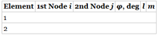
In the finite element model of a plane truss in problem 21, the lengths of elements 1 and 2 are 1 m and
a. Fill in the connectivity information of your choice
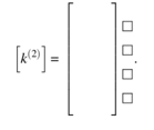
b. Write down the clement stiffness matrix
c. Show where
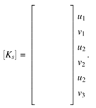
d. The displacements are calculated as:

Trending nowThis is a popular solution!

Chapter 1 Solutions
Introduction To Finite Element Analysis And Design


- Consider the following spring system. ////// m, _with spring constants c = 3 Assume down is the positive direction. Write the stiffness matrix K = 3. • Compute the external force which causes the displacement u = Force =arrow_forwardFor the following system, find the mass matrix [m] and the stiffness matrix [k] and write the differential equations.arrow_forwardDraw the corresponding scheme and find the equation on the right. Method used and Four assumptions hA Tc.v.(t) = Taire + [Tc.v.(tt) – Tairele locp)"arrow_forward
- PROBLEM 2 Determine the internal force of the following members in the structure below. [Select] 1. GI [Select] 2. FH [ Select ] v 3. GH 20 N 40 N 40 N 20 N D 2 m Ao 10 m KOOL Mo NoL 4 m 4 m 4 m 2m -- 2marrow_forwardSuppose that the stiffness matrices of the above question (as shown below) are as follows: b -b a a K1 =108 x K2 =108 x -b -a a b 0.1 m 0.05 m 0.5 m 0.5 m where a= 1.8 N/m and b=2.9 N/m. Find the assembled stiffness matrix of the system using the following connectivity table. Element Node i Node j (1) 2 (2) 2 What is the summation of all terms located on the main diagonal of the assembled [a bc] stiffness matrix? (Hint: if the assembled stiffness matrix is b de then you e f need to find the value of a + d+ f). Your Answer: Answer The shape function value ) is zero at the centre of the element. O is always higher than 1. O is equal 1 at its own node and zero at other nodes. O is always less than 1.arrow_forward3. Jacobian Matrix: a) Derive the equation for Joint Force of the given planar 1R robot. As it's a planar robot, forces at the end-effector are Ex and Ex. b) Find the force (FX) when the link length is 0.5 m, Joint force is 1 Nm, Joint variable, 0 = 60 and Fx = 0 N. T P₂ y r F -F₂ ee 0,0 F Р. X 7 ४arrow_forward
- 1 juin 2021 à 14:47 Calculate the forces occurring in each element of the plane truss system given in the figure according to the nodal point method (Unit: kN). 2 [m] D 5,0 [m] 6,0 Çubuk Kuvveti Şiddeti (kN) Çekme / Basınç SAB SAC SAD SBD ScDarrow_forward(b) A beam is subjected to a linearly increasing distributed load. The elastic curve (deflection) is shown in the figure. The equation to find the maximum deflection is given below. Create a matlab code where you can calculate the maximum deflection (dy/dx=0) using the bisection method. Use initial guesses of 1 and 4, L= 6.46 m, E = 59000 kN/cm2, I=35000 cm4, and w0= 2.5 kN/cm. What will be the value of x (location of maximum deflection) after 14 bisection iteration? wo -23 +2L?x³ – L^x) 120EIL dy wo (-5x4 + 6L²a² – Lª) da 120EIL Choices 1.4445 O 2.6001 O4.3335 O 2.889arrow_forwardols.lhu.edu.lb The frame ABis supported by a pin at A and a pin at B. It is subjected to a concentrated force of P= 60 kN applied at C as shown in the following figure. The horizontal component of reaction at pin A is: 1.5 m Select one: O a. 180 [kN] O b. 45 [kN] c. 90 [kN] O d. 0arrow_forward
- 1- According to the system shown below, determine nodal displacements at node number 1 through 5 in meter. (All details of solution steps should be mentioned) k-80 lb/in kg 120 lb/in 100 lbs. HIH k₁-60 lb/in 180 lb/in ky- 50 lb/in 80 lbs. www k₂= 150 lb/inarrow_forwardProblem 3 There are 520 nodes and 800 brick finite elements in a model. 40 nodes are completely fixed and other 50 are fixed from displacement along x-axis. There are 3 degrees of freedom in a node. What is the number of unknowns in the FE model?arrow_forward2. As a traffic engineer, you have been asked to investigate the dynamic response of the road sign (in Figure a below) to wind gusts. In particular, you are to stu-the bending and torsional response of the support pole for the sign due to initial velocity conditions due to a wind gust (Figure b). Derive the equation of motion using Lagrange's equation and show it in matrix form (neglect gravity). (25) San Diego Fwy Speed Limit 55 (White Ford Broncos 25) (a) Front View (b) Top View G M. Ic 0arrow_forward
 Elements Of ElectromagneticsMechanical EngineeringISBN:9780190698614Author:Sadiku, Matthew N. O.Publisher:Oxford University Press
 Mechanics of Materials (10th Edition)Mechanical EngineeringISBN:9780134319650Author:Russell C. HibbelerPublisher:PEARSON
 Thermodynamics: An Engineering ApproachMechanical EngineeringISBN:9781259822674Author:Yunus A. Cengel Dr., Michael A. BolesPublisher:McGraw-Hill Education
 Control Systems EngineeringMechanical EngineeringISBN:9781118170519Author:Norman S. NisePublisher:WILEY
 Mechanics of Materials (MindTap Course List)Mechanical EngineeringISBN:9781337093347Author:Barry J. Goodno, James M. GerePublisher:Cengage Learning
 Engineering Mechanics: StaticsMechanical EngineeringISBN:9781118807330Author:James L. Meriam, L. G. Kraige, J. N. BoltonPublisher:WILEY