
Concept explainers
Videos
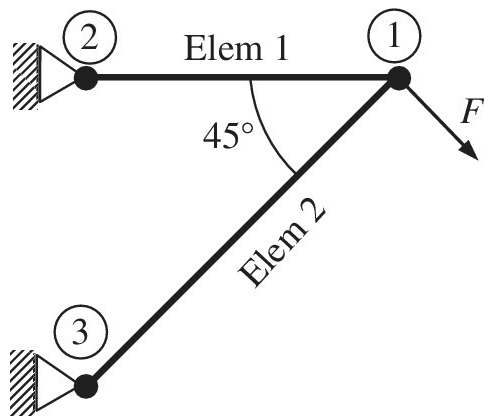
The truss structure shown in the figure supports a force F. The finite element method is used to analyze this structure using two truss elements as shown in the figure. The cross- sectional area for both elements is
a. Compute the transformation matrix [T] for element 2 that enables you to transform between global and local coordinates (as shown in equation below).
b. It is determined after solving the final equations that the displacement components of the node 1 are:
Want to see the full answer?
Check out a sample textbook solution
Chapter 1 Solutions
Introduction To Finite Element Analysis And Design
Additional Engineering Textbook Solutions
Introduction to Heat Transfer
Thinking Like an Engineer: An Active Learning Approach (3rd Edition)
Mechanics of Materials (10th Edition)
Degarmo's Materials And Processes In Manufacturing
Manufacturing Engineering & Technology
Automotive Technology: Principles, Diagnosis, and Service (5th Edition)


- Suppose that the stiffness matrices of the above question (as shown below) are as follows: b -b a a K1 =108 x K2 =108 x -b -a a b 0.1 m 0.05 m 0.5 m 0.5 m where a= 1.8 N/m and b=2.9 N/m. Find the assembled stiffness matrix of the system using the following connectivity table. Element Node i Node j (1) 2 (2) 2 What is the summation of all terms located on the main diagonal of the assembled [a bc] stiffness matrix? (Hint: if the assembled stiffness matrix is b de then you e f need to find the value of a + d+ f). Your Answer: Answer The shape function value ) is zero at the centre of the element. O is always higher than 1. O is equal 1 at its own node and zero at other nodes. O is always less than 1.arrow_forwardConsider the following spring system. ////// m, _with spring constants c = 3 Assume down is the positive direction. Write the stiffness matrix K = 3. • Compute the external force which causes the displacement u = Force =arrow_forward****USE MATLAB TO SOLVE THIS QUESTION**** 5. A composite cantilever beam, made of High Strength (HS) carbon/epoxy material with [04/304], plies, has uniformly applied load go. When qo=50N/m, length of the beam, L=0.1m, and width of the beam, b=0.05m. Find the maximum deflection of the beam. (for the HS carbon fiber/epoxy, E₁1 =131 GPa, E₂2= 11.2 GPa, V12 = 0.28, G12 = 6.55 GPa and ply thickness t=0.2mm) 90-50N/m Larrow_forward
- Find the Global Stiffness Matrix for the following Spring Structure. Use your answer to set up matrix Equation F=KX.arrow_forward1. Three springs, A, B and C, are connected as shown below, with one end of A and C attached to rigid supports. All springs are interconnected by a light, inextensible bar that is constrained from rotating. Also, forces of 250 N and 175 N are applied to the springs as shown. The stiffness of A, B and C are 100, 150 and 200 N/mm, respectively. By modelling each spring as a linear simplex finite element, determine: (a) (b) (c) the global assembly the elongation of the springs the reactions at the supports (Ans: (b) u, = 1.417 mm, u, = 1.667 mm, uc = 11.417 mm (c) Ren = 141.67 N, left, Riaht = 283.33 N, left) B 250 N wwww-→ A 175 Narrow_forwardFind the global stiffness matrix, displacement at node 1&2, reaction forces at 1&4, and force in spring for the following figure shown below. k1=90 N/mm, k2=1800 N/mm, k3=80 N/mm, P=600 N and u1=u4=0arrow_forward
- For the spring system shown in the above figure, determine the displacement of each node. In the figure, the unit for the stiffness k is pound (lb) per inch. The left side of the system is fixed to a rigid wall, while the right side is displaced 0.5 inch to the right. Put a node between the rigid wall on the left and spring 1. Use the element method to establish the element stiffness matrix and then the global stiffness matrix. Apply the boundary conditions and theloads (by modifying the appropriate rows of the matrix and load vector). Solve the set of linear equations either by hand or using Matlab, Mathcad or Maple.arrow_forwardII. A circular column is made of concrete [E. 4.2(103)ksi] while being reinforced with six steel rods [Est = 29 (10³)ksi]. It is acted upon 4 in. 30 kip by an axial force of 30 kip as shown in the figure to the right. Each rod has a diameter of 0.85 in. (L1: 4 pts, L2: 4 pts) 3 ft Solve for the following: a) Force in each steel rod, Pst kip (2 pts, L2) b) Force in the concrete, P. = kip (2 pts, L2) ksi (2 pts, L1) ksi (2 pts, L1) c) Stress in each steel rod, ơst = d) Stress in the concrete, o. =arrow_forwardThree springs with different spring constants are connected as shown below. You are going to use spring elements to simulate this system. Suppose that the spring constants of the first, second and third elements are k1=3,410 N/m, k2=3,160 N/m and k3=3,380 N/m, respectively. Two horizontal forces are applied to the system (as shown) at nodes. 2 and 3. Find the displacement of node 3 and write your answer in mm (millimetre). Hint: Write your answer with 5 decimal places. For example if you calculated the value 1.2345678, then rounding off to 5 decimal places yields 1.23457 and that is the value you need to type in the answer box. U₁=0 (1) F₂ = 2N U₂ = ? F3 = -1N (2) M U3 = ? (3) U4 = 0arrow_forward
- 1. A spring mass system serving as a shock absorber under a car's suspension, supports the M=1000kgmass of the car. For this shock absorber,k=1000N/m and c=2000N s/m. The car drives over a corrugated road with force F=2000sin(wt)N. Use your notes to model the second order differential equation suited to thisapplication. Simplify the equation with the coefficient of x'' as one. Solve x (the general solution) interms of using the complimentary and particular solution method. In determining the coefficients ofyour particular solution, it will be required that you assume w2 -1=w or . Do not 1-w2=-wuse Matlab as its solution will not be identifiable in the solution entry. Do not determine the value of w.You must indicate in your solution:1. The simplified differential equation in terms of the displacement x you will be solving2. The m equation and complimentary solution3. The choice for the particular solution and the actual particular solution xp4. Express the solution x as a piecewise…arrow_forwardConsider the following truss system. All bars are vertical or horizontal. Enter the elongation matrix (A = BT): (in the form "node 1: horiz", "node 1: vert", "node 2: horiz" etc.) A = Compute a basis for the nullspace of A. Basis = Match the following force vectors fm with the motions they would induce and state whether they are in the nullspace of A Motion: Motion: Motion: Motion: ? -1 In nullspace? In nullspace? In nullspace? In nullspace? -1 -2 -1 -1 -1 A B D (Click on a figure to enlarge it)arrow_forwardA rectangular tube of outer width w = 7.5 m, outer height h = 5 m and thickness t = 0.17 m experiences bending through the x axis. What is the moment of inertia of the cross-sectional area In? y -- X MATLAB input variables: format shortEng W = 7.5; h = 5; t = 0.17; moment of inertia I, = m4arrow_forward
 Elements Of ElectromagneticsMechanical EngineeringISBN:9780190698614Author:Sadiku, Matthew N. O.Publisher:Oxford University Press
 Mechanics of Materials (10th Edition)Mechanical EngineeringISBN:9780134319650Author:Russell C. HibbelerPublisher:PEARSON
 Thermodynamics: An Engineering ApproachMechanical EngineeringISBN:9781259822674Author:Yunus A. Cengel Dr., Michael A. BolesPublisher:McGraw-Hill Education
 Control Systems EngineeringMechanical EngineeringISBN:9781118170519Author:Norman S. NisePublisher:WILEY
 Mechanics of Materials (MindTap Course List)Mechanical EngineeringISBN:9781337093347Author:Barry J. Goodno, James M. GerePublisher:Cengage Learning
 Engineering Mechanics: StaticsMechanical EngineeringISBN:9781118807330Author:James L. Meriam, L. G. Kraige, J. N. BoltonPublisher:WILEY