
Videos
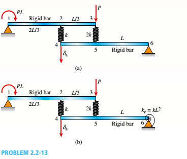
Two rigid bars are connected to each other by two linearly elastic springs. Before loads are applied, the lengths or the springs are such, that the bars are parallel and the springs are without stress.
(a) Derive a formula for the displacement E4at point 4 when the load P is applied at joint 3 and moment PL is applied at joint 1. as shown in the figure part a. (Assume that the bars rotate through very small angles under the action of load P.)
(b) Repeat part (a) if a rotational spring, kr= kL2, is now added at joint 6. What is the ratio of the deflection d4 in the figure part a to that in the figure part b ?
(a)
The formula for the displacement at point
Answer to Problem 2.2.13P
The formula for the displacement at point
Explanation of Solution
Given information:
The load applied at point
The moment art point
The following figure shows the free body diagram of the bar:
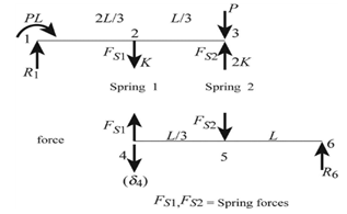
Figure-(1)
Write the expression for the moment equilibrium about support
Here, the reaction at forces in spring
Write the expression for the moment equilibrium about support
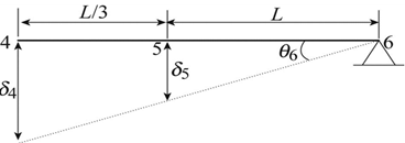
Figure-(2)
Write the expression for deflection
Here, the deflection at point
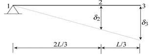
Figure-(3)
Write the expression for deflection
Here, the deflection at point
Write the expression for the spring stiffness.
Here, the spring constant is
Write the expression for the elongation of spring
Write the expression for the elongation of spring
Calculation:
Substitute
Substitute
Substitute
Substitute
Conclusion:
The formula for the displacement at point
(b)
The ratio of deflection at point
Answer to Problem 2.2.13P
The ratio of deflection at point 4 is
Explanation of Solution
Given Information:
The spring constant for rotational spring is
The following figure shows the free body diagram of the bar having rotational spring:
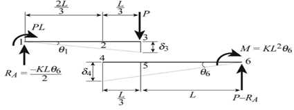
Figure-(4)
Write the expression for the moment equilibrium about support
Here, angle of deflection of beam is
Write the expression for the net elongation of spring
Write the expression for the displacement at point
Write the expression for the displacement at point
Write the expression for the net elongation of spring
Write the expression for displacement at point 3.
Write the expression for displacement at point 5.
The figure below shows the free body diagram of the bar.
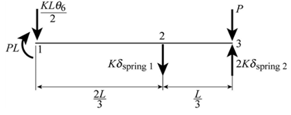
Figure-(5)
Write the expression for the vertical force equilibrium.
Write the expression for the moment equilibrium about point 2.
Write the expression for the angle of deflection of the beam
The following figure shows the forces acting on point
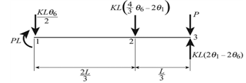
Figure 6
Write the expression for the ratio of deflection of part
Calculation:
Substitute
Substitute
Substitute
Substitute
Conclusion:
The ratio of deflection at point
Want to see more full solutions like this?
Chapter 2 Solutions
Mechanics of Materials (MindTap Course List)


- Around brass bar of a diameter d1= 20mm has upset ends each with a diameter d2= 26 mm (see figure). The lengths of the segments of the bar are L1= 0.3 m and L2= 0.1 m. Quarter-circular fillets are used at the shoulders of the bar, and the modulus of elasticity of the brass is E = 100 GPa. If the bar lengthens by 0.12 mm under a tensile load P, what is the maximum stress ??maxin the bar?arrow_forwardA vertical pole of solid, circular cross section is twisted by horizontal forces P = 5kN acting at the ends of a rigid horizontal arm AB (see figure part a). The distance from the outside of the pole to the line of action of each force is c = 125 mm (sec figure part b) and the pole height L = 350 mm. (a) If the allowable shear stress in the pole is 30 MPa, what is the minimum required diameter dminof the pole? (b) What is the torsional stiffness of the pole (kN · m/rad)? Assume that G = 28 GPa. (c) If two translation al springs, each with stiffness k =2550 kN/m, are added at 2c/5 from A and B (see figure part c), repeat part (a) to find dmin. Hint: Consider the pole and pair of springs as "springs in parallel."arrow_forwardTwo pipe columns (AB, FC) are pin-connected to a rigid beam (BCD), as shown in the figure. Each pipe column has a modulus of E, but heights (L1or L2) and outer diameters (d1or different for each column. Assume the inner diameter of each column is 3/4 of outer diameter. Uniformly distributed downward load q = 2PIL is applied over a distance of 3L/4 along BC, and concentrated load PIA is applied downward at D. (a) Derive a formula for the displacementarrow_forward
- A vertical pole of solid, circular cross section is twisted by horizontal forces P = 1100 lb acting at the ends of a rigid horizontal arm AB (see figure part a). The distance from the outside of the pole to the line of action of each force is c = 5.0 in. (see figure part b) and the pole height is L = 14in. (a) If the allowable shear stress in the pole is 4500 psi, what is the minimum required diameter dminof the pole? Find the torsional stiffness of the pole (kip-in./rad). Assume that G = 10,800 ksi. If two translational springs, each with stiffness k = 33 kips/in., are added at 2(75 from A and B (see figure part c), repeat part (a) to find dmin. Hint: Consider the pole and pair of springs as "springs in parallel."arrow_forwardA square steel tube of a length L = 20 ft and width b2= 10.0 in. is hoisted by a crane (see figure). The lube hangs from a pin of diameter d that is held by the cables at points A and B. The cross section is a hollow square with an inner dimension b1= 8.5 in. and outer dimension b2= 10,0 in. The allowable shear stress in the pin is 8,700 psi. and the allowable bearing stress between the pin and the tube is 13,000 psi. Determine the minimum diameter of the pin in order to support the weight of the tube. Note: Disregard the rounded corners of the tube when calculating its weight.arrow_forwardA long, slender bar in the shape of a right circular cone with length L and base diameter d hangs vertically under the action of its own weight (see figure). The weight of the cone is W and the modulus of elasticity of the material is E. Derive a formula for the increase S in the length of the bar due to its own weight. (Assume that the angle of taper of the cone is small.)arrow_forward
- A tubular bar with outside diameterd2= 4.0 in, is twisted by torques T = 70,0 kip-in. (see figure). Under the action of these torques, the maximum tensile stress in the bar is found to be 6400 psi. Determine the inside diameter rtf of the bar. If the bar has length L = 48.0 in. and is made of aluminum with shear modulus G = 4,0 × 10⁶ psi, what is the angle of twist d (in degrees) between the ends of the bar? (c) Determine the maximum shear strain y (in radians)?arrow_forwardA flat brass bar has length L, constant thickness t, and a rectangular cross section whose width varies linearly between b2at the fixed support to b1at the free end (see figure). Assume that the taper of the bar is small. The bar has modulus of elasticity E. Calculate the displacements ??Band ??cif P = 200 kN, L = 2 m, t = 20 mm, b, = 100 mm, b, = 115 mm, and E = 96 GPa.arrow_forwardA solid circular bar of steel (G = 1L4 × 106 psi) with length L = 30 in, and diameter d = 1.75 in, is subjected to pure torsion by torques T acting at the ends (see figure). Calculate the amount of strain energy V stored in the bar when the maximum shear stress is 4500 psi. From the strain energy, calculate the angle of twist 0 (in degrees).arrow_forward
- A uniformly tapered lube AB of circular cross section and length L is shown in the figure. The average diameters at the ends are dAand d£= 2d t. Assume E is constant. Find the elongation S of the tube when it is subjected to loads P acting at the ends. Use the following numerical data:^ = 35 mm, L = WO mm, E = 2.1 GPa. and P = 25 tN. Consider the following cases. (a) A hole of constant diameter dAis drilled from B toward A to form a hollow section of length x - U2. (b) A hole of variable diameter a\.x) is drilled, from B toward A to form a hollow section of length x = L/2 and constant thickness t = dA/20.arrow_forwardA bar ABC revolves in a horizontal plane about a vertical axis at the midpoint C (see figure). The bar, which has a length 2L and crass-sectional area A, revolves at constant angular speed at. Each half of the bar (AC and BC) has a weight W, and supports a weight W2at its end. Derive the following formula for the elongation of one-half of the bar (that is. the elongation of either AC ar BC). =L223gEA(w1+3w2) in which E is t he modulus of elasticity of the material of the bar and g is the acceleration of gravity.arrow_forward-8 An aluminum bar of solid circular cross section is twisted by torques T acting at the ends (see figure). The dimensions and shear modulus of elasticity arc L = 1.4 m, d = 32 mm, and G = 28 GPa. Determine the torsional stiffness of the bar. If the angle of twist of the bar is 5º, what is the maximum shear stress? What is the maximum shear strain (in radians)? If a hole of diameter d/2 is drilled longitudinally through the bar, what is the ratio of the torsional stiffnesses of the hollow and solid bars? What is the ratio of their maximum shear stresses if both arc acted on by the same torque? If the hole diameter remains at d/2, what new outside diameter d2will result in equal stiffnesses of the hollow and solid bars?arrow_forward
 Mechanics of Materials (MindTap Course List)Mechanical EngineeringISBN:9781337093347Author:Barry J. Goodno, James M. GerePublisher:Cengage Learning