
Concept explainers
Videos
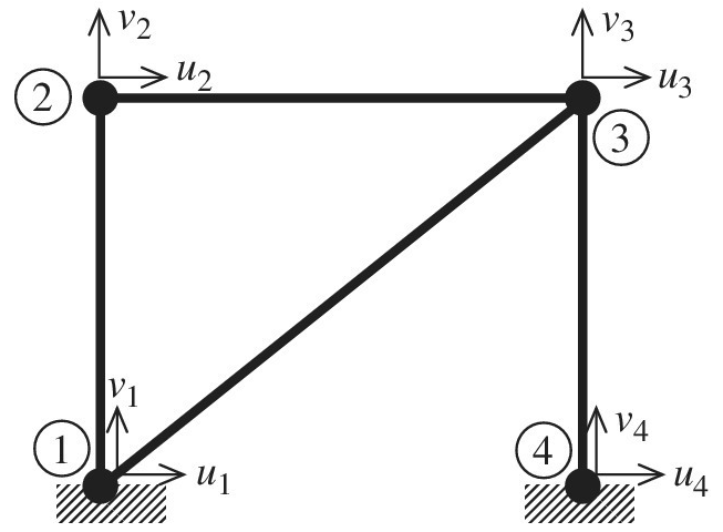
The 2D truss shown in the figure is assembled to build the global matrix equation. Before applying boundary conditions, the dimension of the global stiffness matrix is
Want to see the full answer?
Check out a sample textbook solution
Chapter 1 Solutions
Introduction To Finite Element Analysis And Design


- Q4: Calculate elastic compliance constants (S's) related to C's in the following matrix. [C11 C12 C13] C21 C22 C23 C31 C32 C33arrow_forwardii, If the length of each element is 5m and the k-EA/L is given as shown, analyze the following system by Direct Method of Finite Element. ki - 200 kN/m * - 1000 kN/m ky : 300 kN/m 400 kN 2 Develop the displacement vector b. Develop the force vectors | c. Develop the stifness matrix for each element d. Develop the global matrix for the sytem e. Find the displacement at node 2 £ Find the forces at node 1 and 3.arrow_forward****USE MATLAB TO SOLVE THIS QUESTION**** 5. A composite cantilever beam, made of High Strength (HS) carbon/epoxy material with [04/304], plies, has uniformly applied load go. When qo=50N/m, length of the beam, L=0.1m, and width of the beam, b=0.05m. Find the maximum deflection of the beam. (for the HS carbon fiber/epoxy, E₁1 =131 GPa, E₂2= 11.2 GPa, V12 = 0.28, G12 = 6.55 GPa and ply thickness t=0.2mm) 90-50N/m Larrow_forward
- 3. Answer the question completely and write down the given, required and formula that had been used. Provide graph and accurate/comple solution. The value are: V- 1 X- 5 W- 7 Y- 6 Z- 8arrow_forwardPlease Draw The Freebody On a sheet of paper Only and Solve via Handwritten Only. Here I am facing difficulty in Typed based solution. [Reaction(N) and angle(°)]arrow_forward2) The vertices of a wedge are given in the matrix show below. Rotate the wedge 30* CCW around the x-axis and then 45° CW around the y-axis. r0 0 0 0 0 11 4 0 0 [P] 4 0 2 0 3 o 3 0.arrow_forward
- Points for stress vs strain (in image) Assume the compressive concrete strength (f’c) is 3,000 lb/in2 (psi)Calculate a cubic function (3rd order polynomial – Ax3+Bx2+Cx+Constant)Use this function to create a function that describes the slope of the cubic function (the derivative of thecubic function). This new function allows you to calculate the tangent to any point along the curve. Thetangent is the modulus of elasticity (E). The concrete code provides a formula to calculate E for concrete. That formula is:E = 57,000√??′, where f’c is in units of psi, and E is in units of psi.Use the derivative function you calculated to locate the point on the curve where the slope of the curvematches E using the concrete code formula. Express that stress point on the curve as a percentage ofthe compressive strength of the concrete. Now, calculate the secant modulus for the test case using 1,500 psi (50% f’c) as the arbitrary point onthe curve.Assume fracture occurs at the last point…arrow_forwardQ3/For the network shown in the figure below, write nodal equations. R₂ www 20 Ry R₁' 103 www I 193 2 A Rs 100 Rs R3 www 20♫arrow_forwardConsider the following truss system. All bars are vertical or horizontal. Enter the elongation matrix (A = BT): (in the form "node 1: horiz", "node 1: vert", "node 2: horiz" etc.) A = Compute a basis for the nullspace of A. Basis = Match the following force vectors fm with the motions they would induce and state whether they are in the nullspace of A Motion: Motion: Motion: Motion: ? -1 In nullspace? In nullspace? In nullspace? In nullspace? -1 -2 -1 -1 -1 A B D (Click on a figure to enlarge it)arrow_forward
- Q1: * Q1 Calculate The Inverse Of The Matrix: [4 A= 2 -2 11 4 4 3 1 Add file Q2: * Using Green's theorem, evaluate the line integral (y- a)dr- (x +y°)dy, where the contour C encloses the sector of the circle with radius a lying in the first quadrant 0 = 1/2 R >-0 aarrow_forwardihài 25 Q3) Let vector A = 5i +2j, Vector B = -3i %3D -5j, and vector C = A+ B. (a) Write %3D vector C in component form. (b) Draw a coordinate system and on it show the all vectors. (c) What are the ?magnitude and direction of vector Carrow_forwardFor the given 2D element shown in the diagram with positions A = 5 m and B = 5 m, answer the following: a) X (0,B) 1 2 (0,0) 3 (A,B) DIAGRAM NOT TO SCALE Write the expression of basis function associated with point 1, in terms of x and y Submit part Unanswered b) The displacement of node 3 is 0.3 m in the x direction, and 0 in the y. All other node displacements are zero. What is the normal strain component across the element? Submit part Unansweredarrow_forward
 Elements Of ElectromagneticsMechanical EngineeringISBN:9780190698614Author:Sadiku, Matthew N. O.Publisher:Oxford University Press
 Mechanics of Materials (10th Edition)Mechanical EngineeringISBN:9780134319650Author:Russell C. HibbelerPublisher:PEARSON
 Thermodynamics: An Engineering ApproachMechanical EngineeringISBN:9781259822674Author:Yunus A. Cengel Dr., Michael A. BolesPublisher:McGraw-Hill Education
 Control Systems EngineeringMechanical EngineeringISBN:9781118170519Author:Norman S. NisePublisher:WILEY
 Mechanics of Materials (MindTap Course List)Mechanical EngineeringISBN:9781337093347Author:Barry J. Goodno, James M. GerePublisher:Cengage Learning
 Engineering Mechanics: StaticsMechanical EngineeringISBN:9781118807330Author:James L. Meriam, L. G. Kraige, J. N. BoltonPublisher:WILEY