
Concept explainers
Videos
A circular bar ACB of a diameter d having a cylindrical hole of length .r and diameter till from A to C is held between rigid supports at A and B. A load P acts at U2from ends A and B. Assume E is constant.
(a) Obtain formulas for the reactions R, and RBat supports A and B. respectively, due to the load P (see figure part a).
(b) Obtain a formula for the displacement S at the point of load application (see figure part a).
(c) For what value of x is RB= (6/5)?,? (See figure part a.)
(d) Repeat part (a) if the bar is now rotated to a vertical position, load P is removed, and the bar is hanging under its own weight (assume mass density = p). (See figure part b.) Assume that
x = LI2.
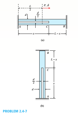
(a)
The formulas for the reactions at the point A and point B due to the load.
Answer to Problem 2.4.7P
The reaction force at point B is
The reaction force at point A is
The reaction force at point B is
The reaction force at point A is
Explanation of Solution
Given information:
The Diameter of circular bar is
The figure below shows the free body diagram of the bar.
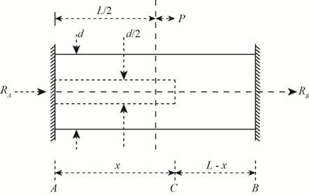
Figure-(1)
Write the expression for the area when
Here, the area of the section AC is
Write the expression for the elongation of the bar at point B .
Here, load is
Write the expression for the area of bar CB when
Write the expression for the elongation at point B .
Write the expression for the elongation at point B in terms of the reaction force.
Here, the reaction force at point B is
Write the compatibility equation if
Write the expression for the rod held under rigid supports if
Write the expression for the force balance in horizontal direction.
Here, the reaction force at point A is
Calculation:
Substitute
Substitute
Substitute
Substitute
Substitute
Substitute
Conclusion:
The reaction force at point B is
The reaction force at point A is
The reaction force at point B is
The reaction force at point A is
(b)
The formula for the displacement at the point of load.
Answer to Problem 2.4.7P
The displacement at the point of load is
The displacement at the point of load is
The displacement at the point of load is
Explanation of Solution
Write the expression for the displacement at the point of load if
Here, the reaction force at point A is
Write the expression for the load at point if
Here, the reaction force at point A is
Calculation:
Substitute
Substitute
Substitute
Substitute
Conclusion:
The displacement at the point of load is
The displacement at the point of load is
The displacement at the point of load is
(c)
The value of
Answer to Problem 2.4.7P
The value of
The value of
Explanation of Solution
Write the expression for the reaction force at B if
Write the expression for the reaction force at B case if
Calculation:
Substitute
Substitute
Conclusion:
The value of
The value of
(d)
The formulas for the reactions at the point A and point B due to the load.
Answer to Problem 2.4.7P
The reaction force at point B is
The reaction force at point A is
Explanation of Solution
Given information:
The bar is placed vertically.
The below figure shows the free body diagram of the bar.
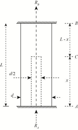
Figure-(2)
Write the compatibility equation if 
Write the expression for the elongation at point B in terms of the reaction force.
Write the expression for the elongation of the bar at point B .
Here, the axial stress in section AC is
Write the expression for the axial stress in section AC is
Here, the density is
Write the expression for the axial stress in section CB is
Write the expression for the elongation of the bar held between rigid bars.
Write the expression for the reaction at point A .
Here, the weight of the bar of section AC is
Write the expression for the weight of the bar of section AC .
Write the expression for the weight of the bar of section CB .
Substitute
Calculation:
Substitute 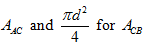 in Equation (XVII).
Substitute  in Equation (XIX).
Substitute in Equation (XX).
Substitute, 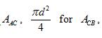
Integrate the Equation (XXIV).
Substitute
Substitute
Substitute 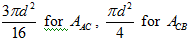 in Equation ......(XXV).
Conclusion:
The reaction force at point B is
The reaction force at point A is
Want to see more full solutions like this?
Chapter 2 Solutions
Mechanics of Materials (MindTap Course List)


- Segments A B and BCD of beam A BCD are pin connected at x = 4 m. The beam is supported by a sliding support at A and roller supports at C and D (see figure). A triangularly distributed load with peak intensity of SO N/m acts on EC. A concentrated moment is applied at joint D. (a) Find reactions at supports A, C, and D. (b) Find internal stress resultants N, Y, and Mat x = 5m. (c) Repeat parts (a) and (b) for die case of the roller support at C replaced by a linear spring of stiffness kr™ 200 kN/m (see figure).arrow_forwardA rigid bar AB having a mass M = 1.0 kg and length L = 0.5 m is hinged at end A and supported at end B by a nylon cord BC (see figure). The record has cross-sectional area A = 30 mm2. length b = 0.25 m. and modulus of elasticity E = 2.1 GPa. If the bar is raised to its maximum height and then released, what is the maximum stress in the cord?arrow_forwardTwo pipe columns (AB, FC) are pin-connected to a rigid beam (BCD), as shown in the figure. Each pipe column has a modulus of E, but heights (L1or L2) and outer diameters (d1or different for each column. Assume the inner diameter of each column is 3/4 of outer diameter. Uniformly distributed downward load q = 2PIL is applied over a distance of 3L/4 along BC, and concentrated load PIA is applied downward at D. (a) Derive a formula for the displacementarrow_forward
- Solve the preceding problem for a W 250 × 89 steel column having a length L = 10 m. Let E = 200 GPa.arrow_forwardA column ABC is supported at ends A and C and compressed by an axial load P (figure a). Lateral support is provided at point B but only in the plane of the figure; lateral support perpendicular to the plane of the figure is provided only at A and C. The column is constructed of two channel sections (C 6 × 8.2) back to back (see figure b). The modulus of elasticity of the column is E = 29,500 ksi and the proportional limit is 50 ksi. The height of the column is L = 15 ft. Find the allowable value of load P using a factor of safety of 2.5.arrow_forwardA plane frame is restrained al joints A and C, as shown in the figure. Members AB and BC are pin connected at B. A triangularly distributed lateral load with a peak intensity or 90 lb/ft acts on AB. A concentrated moment is applied at joint C. (a) Find reactions at supports A and C. (b) Find internal stress resultants A', V, and \f at x = 3 ft on column AB.arrow_forward
- *16 A prismatic bar AB of length L, cross-sectional area A, modulus of elasticity E, and weight Changs vertically under its own weight (see figure). (a) Derive a formula for the downward displacement Scof point E. located at distance It from the lower end of the bar. (b) What is the elongation SBof the entire bar? (c) What is the ratio £ of the elongation, of the upper half of the bar to the elongation of the lower half of the bar? (d) If bar A B is a riser pipe hanging from a drill rig at sea. what is the total elongation of the pipe? Let L = 1500 m, A - 0.ol57 m2, and E = 210 GPa. See Appendix 1 for weight densities of steel and sea water. (See Probs. 1.4-2 and J.7-13 for additional figures.)arrow_forwardAn aluminum bar AD (see figure) has a cross-sectional area of 0.40 in- and is loaded by Forces Pi= 1700 lb, Pz- 1200 lb, and P3 = 1300 lb. The lengths of the segments of the bar are ti = 60 in., b = 24 in.T and c = 36 in. (a) Assuming that the modulus of elasticity is E = 10.4 × 10o psi. calculate the change in length of the bar. Does the bar elongate or shorten? (b) By what amount ^should the load Pibe increased so that the bar does not change in length when the three loads are applied? (c) IF Pzremains at 1300 lb, what revised cross-sectional area For segment AB will result in no change of length when all three loads are applied?arrow_forwardA rigid triangular frame is pivoted at C and held by two identical horizontal wires at points A and B (see figure). Each wire has an axial rigidity EA = 120 kips and coefficient of thermal expansion a = 12.5 X 10⁻⁶/°F. (a) If a vertical load P = 500 lb acts at point D, what are the tensile forces TAand TBin the wires at A and B, respectively? (b) If both wires have their temperatures raised by 180°F while the load P is acting, what are the forces TAand TB (c) What further increase in temperature will cause the wire at B to become slack?arrow_forward
- A rectangular bar of length L has a slot in the middle half of its length (see figure). The bar has width ft, thickness t. and modulus of elasticity E. The slot has width ft/4. (a) Obtain a formula for the elongation E of the bar due to the axial loads P. (b) Calculate the elongation of the bar if the material is high-strength steel, the axial stress in the middle region is 160 MPa. the length is 750mm, and the modulus of elasticity is 210 GPa. (c) IF the total elongation of the bar is limited lo 3^ = 0.475 mm, what is the maximum length of the slotted region? Assume that the axial stress in the middle region remains at 160 MPa.arrow_forwardA long, rectangular copper bar under a tensile load P hangs from a pin that is supported by two steel posts (see figure). The copper bar has a length of 2.0 m, a cross-sectional area of4S00 mm", and a modulus of elasticity Ec= 120 GPa. Each steel post has a height of 0.5 m, a cross-sectional area of 4500 mm2, and a modulus of elasticity E = 200 GRa. (a) Determine the downward displacementarrow_forwardA steel riser pipe hangs from a drill rig located offshore in deep water (see figure). Separate segments are joined using bolted flange plages (see figure part b and photo). Assume that there are six bolts at each pipe segment connection. Assume that the total length of the riser pipe is L = 5000 ft: outer and inner diameters are d2= l6in.and d1= 15 in.; flange plate thickness t1= 1.75 in.; and bolt and washer diameters are db= 1.125 in..and dW. = 1.875 in., respectively. (a) If the entire length of the riser pipe is suspended in air. find the average normal stress a in each bolt, the average bearing stress abbeneath each washer, and the average shear stress t through the flange plate at each bolt location for the topmost bolted connection. (b) If the same riser pipe hangs from a drill rig at sea. what are the normal, bearing, and shear stresses in the connection? Obtain the weight densities of steel and sea water from Table I-1. Appendix I. Neglect the effect of buoyant foam casings on the riser pipearrow_forward
 Mechanics of Materials (MindTap Course List)Mechanical EngineeringISBN:9781337093347Author:Barry J. Goodno, James M. GerePublisher:Cengage Learning