
Principles and Applications of Electrical Engineering
6th Edition
ISBN: 9780073529592
Author: Giorgio Rizzoni Professor of Mechanical Engineering, James A. Kearns Dr.
Publisher: McGraw-Hill Education
expand_more
expand_more
format_list_bulleted
Concept explainers
Videos
Textbook Question
Chapter 2, Problem 2.11HP
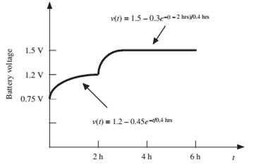
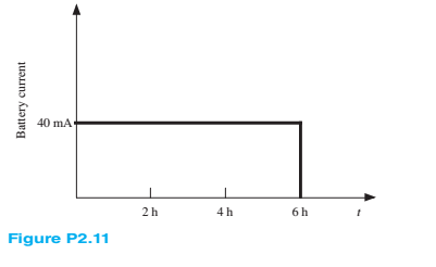
The charging scheme used in Figure P2.11 is anexample of a constant-current charge cycle. The charger voltage is controlled such that the current into the battery is held constant at 40 mA, as shown in Figure P2.11. The battery is charged for 6 h. Find:
a. The total charge delivered to the battery.
b. The energy transferred to the battery during the charging cycle.
Hint: Recall that the energy w is the integral of power, or
Expert Solution & Answer
Want to see the full answer?
Check out a sample textbook solution
Students have asked these similar questions
Steady current circulation is desired for a lamp connected in a circuit to light. For this, explain how a stable current will occur from any part of the circuit with the conservation law of the charge.
Give me detail pls.
a) Find and explain the Ohm conservation expression.b) Stable current circulation is desired for the lamp connected in a circuit to light. Accordingly, discuss with the conservation law of the charge how a stable current circulation can occur from any part of the circuit.I need to explain the answers to these questions, please can you explain in detail. Thanks in advance.
The charge cycle shown in Figure is an exampleof a two-rate charge. The current is held constant at50 mA for 5 h. Then it is switched to 20 mA for thenext 5 h. Find: a. The total charge transferred to the battery.b. The energy transferred to the battery.
Chapter 2 Solutions
Principles and Applications of Electrical Engineering
Ch. 2 - A free electron has an initial potential energy...Ch. 2 - The units for voltage, current, and resistance are...Ch. 2 - A particular fully charged battery can deliver...Ch. 2 - The charge cycle shown in Figure P2.4 is an...Ch. 2 - Batteries (e.g., lead-acid batteries) store...Ch. 2 - What determines: a. The current through an ideal...Ch. 2 - An automotive battery is rated at 120 A-h. This...Ch. 2 - A car battery kept in storage in the basement...Ch. 2 - Suppose the current through a wire is given by the...Ch. 2 - The charge cycle shown in Figure P2.10 is...
Ch. 2 - The charging scheme used in Figure P2.11 is...Ch. 2 - The charging scheme used in Figure P2.12 is...Ch. 2 - Use KCL to determine the unknown currents in the...Ch. 2 - Use KCL to find the current i1 and i2 in Figure...Ch. 2 - Use KCL to find the current i1,i2, and i3 in the...Ch. 2 - Use KVL to find the voltages v1,v2, and v3 in...Ch. 2 - Use KCL to determine the current i1,i2,i3, and i4...Ch. 2 - In the circuits of Figure P2.18, the directions...Ch. 2 - Find the power delivered by each source in Figure...Ch. 2 - Determine whether each element in Figure P2.20 is...Ch. 2 - In the circuit of Figure P2.21, determine the...Ch. 2 - For the circuit shown in Figure P2.22: a....Ch. 2 - For the circuit shown in Figure P2.23,...Ch. 2 - For the circuit shown in Figure P2.24, determine...Ch. 2 - For the circuit shown in Figure P2.25, determine...Ch. 2 - Prob. 2.26HPCh. 2 - Prob. 2.27HPCh. 2 - Prob. 2.28HPCh. 2 - Prob. 2.29HPCh. 2 - Prob. 2.30HPCh. 2 - Prob. 2.31HPCh. 2 - In the circuit of Figure P2.32, assume v2=vs/6 and...Ch. 2 - Prob. 2.33HPCh. 2 - An incandescent light bulb rated at 100 W will...Ch. 2 - An incandescent lightbulb rated at 60 W...Ch. 2 - Refer to Figure P2.36, and assume that...Ch. 2 - Refer to Figure P2.37, and assume that...Ch. 2 - Refer to Figure P2.38, and assume...Ch. 2 - Prob. 2.39HPCh. 2 - With no load attached, the voltage at the...Ch. 2 - Prob. 2.41HPCh. 2 - For the circuits of Figure P2.42, determine the...Ch. 2 - At an engineering site, a 1-hp motor is placed...Ch. 2 - Cheap resistors are fabricated by depositing a...Ch. 2 - Prob. 2.45HPCh. 2 - Use KCL and Ohm’s law to determine the current...Ch. 2 - Refer to Figure P2.13. Assume R0=1,R1=2,R2=3,R3=4...Ch. 2 - Apply KCL and Ohm’s law to find the power supplied...Ch. 2 - Refer to Figure P2.49 and assume...Ch. 2 - Refer to Figure P2.49 and assume...Ch. 2 - Prob. 2.51HPCh. 2 - The voltage divider network of Figure P2.52 is...Ch. 2 - Find the equivalent resistance seen by the source...Ch. 2 - Find the equivalent resistance seen by the source...Ch. 2 - In the circuit of Figure P2.55, the power absorbed...Ch. 2 - Find the equivalent resistance between terminals...Ch. 2 - For the circuit shown in Figure P2.57, find the...Ch. 2 - For the circuit shown in Figure P2.58,find the...Ch. 2 - Refer to Figure P2.59. Assume...Ch. 2 - Find the equivalent resistance seen by the source...Ch. 2 - For the circuit shown in Figure P2.61. assume...Ch. 2 - Determine the equivalent resistance of the...Ch. 2 - For the circuit shown in Figure P2.58, assume...Ch. 2 - In the circuit of Figure P2.64, find the...Ch. 2 - Refer to Figure P2.64 and determine the equivalent...Ch. 2 - Find the equivalent resistance seen by the source...Ch. 2 - Determine the voltage vo between nodes A and Bin...Ch. 2 - Refer to Figure P2.68 and assume...Ch. 2 - Prob. 2.69HPCh. 2 - Prob. 2.70HPCh. 2 - Prob. 2.71HPCh. 2 - The circuit of Figure P2.72 is used to measure the...Ch. 2 - Consider the practical ammeter, depicted in Figure...Ch. 2 - Prob. 2.74HPCh. 2 - Prob. 2.75HPCh. 2 - Prob. 2.76HPCh. 2 - A voltmeter is used to determine the voltage...Ch. 2 - Prob. 2.78HPCh. 2 - Figure P2.79 shows an aluminum cantilevered beam...Ch. 2 - Refer to Figure P2.79 but assume that the...
Knowledge Booster


Learn more about
Need a deep-dive on the concept behind this application? Look no further. Learn more about this topic, electrical-engineering and related others by exploring similar questions and additional content below.Similar questions
- sketch vL1 and vR2 on a graph. mark the labels in microseconds one time constant after the charging phase begins and the value of each voltage at that timearrow_forwardA practical voltmeter has an internal resistance rm.What is the value of rm if the meter reads 11.81 Vwhen connected as shown in Figure P2.75.arrow_forwardFigure 2.1 shows a simple circuit. Explain why using a DMM tomeasure the DC voltage across resistor R2 might lead to inaccurate results. Include in your answer how the value of R2 might affect the size of the error and provide some circuit diagrams and equations to showhow to calculate the error.arrow_forward
- Consider the circuit shown in Figure P1.61. Find the power for the voltage source and for the current source. Which source is absorbing power?arrow_forwardThe charging scheme used in Figure is calleda tapered-current charge cycle. The current starts atthe highest level and then decreases with time for theentire charge cycle, as shown. The battery is chargedfor 12 h. Find:a. The total charge delivered to the battery.b. The energy transferred to the battery during thecharging cycle.arrow_forwardNote that the charge Q all came from the power supply through the resistor ) During the chargingthe power delivered by the supply is P = IV The energy delivered by the supply is powerxtime, or since lis varying during charging E=V int I dt=VQ since I is just charge per time. Compute the energy E = VQ delivered by the supply and compare with the energy of the fully-charged capacitorWhat happened to the rest of the energy? %3D Transient RC response. Consider the following circuit with R-1 k2, C=0.1 µF and V-10 Volts. Initially the capacitor is discharged (Vc-0) and the switch is open as shown, so no current flows. At time t-0 the switch is closed, allowing current to flow through the resistor and charge up the capacitor. Rarrow_forward
- Cyclic Voltammetry and Charge-discharge The given figure is the Galvanostatic Charge-discharge curves of a supercapacitor made with MnO2 coated on a CNT electrode. Potential is measured with respect to time by applying different current densities. Based on the plot, answer the following questions 4. Is it possible to estimate maximum power of the device with this charge-discharge curve? If possible, explain how you would do it. (calculation is not necessary)arrow_forwardFor the circuit shown in Figure P1.77, solve for the current i x. What types of sources are present in this circuit?arrow_forwardFor the circuit shown in Figure P1.76, solve for i s. What types of sources are present in this circuit?arrow_forward
- 1.4 The charge cycle shown in Figure PL4 is an example of a three-rate charge. The current is held constant at 30 mA for 6 h. Then it is switched to 20 mA for the next 3 h. Find: a. The total charge transferred to the battery. b. The energy transferred to the battery.Page 58 Hint: Recall that energy w is the integral of power, or P = dw/dr. 1.7 V 1.2 V 9.6V 05 V 30 mA 20 mA Figure P14 3h 3h 6h 6h 9h 7arrow_forward(b) The simple DC circuit in Figure 2.0 is powered by a 15 volts DC battery input-source (V₁) which will cause currents to flow through the resistors, R₁, R₂ and R3 as illustrated. When current flows through a resistor, it creates a voltage across the resistor as governed by the Ohm's Law expression, V = I.R. The Kirchhoff's Current Law (KCL) states that the sum of all currents entering (or leaving) a node is zero. Therefore, I₁ + (- 1₂) + (-13) = 0, resulting in I₁ = I₂ + 13. Even though the basic circuit laws may not be fully covered in class as yet, you may use the above circuit law expressions to determine the missing values in Table 2.0. Show your analysis on the below workspace provided. Note: 1 mA = 1x10-³A = 0.001A; and 1 kQ=1x10³Q=1000Q Pre-Lab workspace V₁ (15 volts) V₂ V3 5 volts ←4₂₁₂ Table 2.0 + I₁ R₁ (10 km) www V₁ Figure 2.0: Simple D.C. circuit for voltage and current measurements R₂ (10 kn) I₂ 0.5 mA ↓ 13 + R3 (10 ΚΩ) What relationship exists between voltages V₂ and…arrow_forward1. Clear All in the simulation. Add a positive and negative charge as shown in the diagram below. Plot equipotential lines in 10 V increments. Note: For this exercise the potential do not need to be precise; the patterns will still be evident if you are within +/-0.5 V plot clear equipotential OV voltage Are the equipotential lines evenly spaced (this would suggest a linear relationship) or exponential?arrow_forward
arrow_back_ios
SEE MORE QUESTIONS
arrow_forward_ios
Recommended textbooks for you
 Introductory Circuit Analysis (13th Edition)Electrical EngineeringISBN:9780133923605Author:Robert L. BoylestadPublisher:PEARSON
 Delmar's Standard Textbook Of ElectricityElectrical EngineeringISBN:9781337900348Author:Stephen L. HermanPublisher:Cengage Learning
 Programmable Logic ControllersElectrical EngineeringISBN:9780073373843Author:Frank D. PetruzellaPublisher:McGraw-Hill Education
 Fundamentals of Electric CircuitsElectrical EngineeringISBN:9780078028229Author:Charles K Alexander, Matthew SadikuPublisher:McGraw-Hill Education
 Electric Circuits. (11th Edition)Electrical EngineeringISBN:9780134746968Author:James W. Nilsson, Susan RiedelPublisher:PEARSON
 Engineering ElectromagneticsElectrical EngineeringISBN:9780078028151Author:Hayt, William H. (william Hart), Jr, BUCK, John A.Publisher:Mcgraw-hill Education,
Introductory Circuit Analysis (13th Edition)
Electrical Engineering
ISBN:9780133923605
Author:Robert L. Boylestad
Publisher:PEARSON
Delmar's Standard Textbook Of Electricity
Electrical Engineering
ISBN:9781337900348
Author:Stephen L. Herman
Publisher:Cengage Learning
Programmable Logic Controllers
Electrical Engineering
ISBN:9780073373843
Author:Frank D. Petruzella
Publisher:McGraw-Hill Education
Fundamentals of Electric Circuits
Electrical Engineering
ISBN:9780078028229
Author:Charles K Alexander, Matthew Sadiku
Publisher:McGraw-Hill Education
Electric Circuits. (11th Edition)
Electrical Engineering
ISBN:9780134746968
Author:James W. Nilsson, Susan Riedel
Publisher:PEARSON
Engineering Electromagnetics
Electrical Engineering
ISBN:9780078028151
Author:Hayt, William H. (william Hart), Jr, BUCK, John A.
Publisher:Mcgraw-hill Education,
How does an Alternator Work ?; Author: Lesics;https://www.youtube.com/watch?v=tiKH48EMgKE;License: Standard Youtube License