
Principles and Applications of Electrical Engineering
6th Edition
ISBN: 9780073529592
Author: Giorgio Rizzoni Professor of Mechanical Engineering, James A. Kearns Dr.
Publisher: McGraw-Hill Education
expand_more
expand_more
format_list_bulleted
Videos
Textbook Question
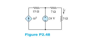
Chapter 2, Problem 2.48HP
Apply KCL and Ohm’s law to find the power supplied by the voltage source in Figure P2.48.Assume
Expert Solution & Answer
Want to see the full answer?
Check out a sample textbook solution
Students have asked these similar questions
Steady current circulation is desired for a lamp connected in a circuit to light. For this, explain how a stable current will occur from any part of the circuit with the conservation law of the charge.
Give me detail pls.
Electric Current and Resistance.
What is an Electric Battery?
Define electric current and state what is meant by the term conventional current.
Describe Ohms's Law and draw an example using an I-V cuvre.
Figure 2.1 shows a simple circuit. Explain why using a DMM tomeasure the DC voltage across resistor R2 might lead to inaccurate results. Include in your answer how the value of R2 might affect the size of the error and provide some circuit diagrams and equations to showhow to calculate the error.
Chapter 2 Solutions
Principles and Applications of Electrical Engineering
Ch. 2 - A free electron has an initial potential energy...Ch. 2 - The units for voltage, current, and resistance are...Ch. 2 - A particular fully charged battery can deliver...Ch. 2 - The charge cycle shown in Figure P2.4 is an...Ch. 2 - Batteries (e.g., lead-acid batteries) store...Ch. 2 - What determines: a. The current through an ideal...Ch. 2 - An automotive battery is rated at 120 A-h. This...Ch. 2 - A car battery kept in storage in the basement...Ch. 2 - Suppose the current through a wire is given by the...Ch. 2 - The charge cycle shown in Figure P2.10 is...
Ch. 2 - The charging scheme used in Figure P2.11 is...Ch. 2 - The charging scheme used in Figure P2.12 is...Ch. 2 - Use KCL to determine the unknown currents in the...Ch. 2 - Use KCL to find the current i1 and i2 in Figure...Ch. 2 - Use KCL to find the current i1,i2, and i3 in the...Ch. 2 - Use KVL to find the voltages v1,v2, and v3 in...Ch. 2 - Use KCL to determine the current i1,i2,i3, and i4...Ch. 2 - In the circuits of Figure P2.18, the directions...Ch. 2 - Find the power delivered by each source in Figure...Ch. 2 - Determine whether each element in Figure P2.20 is...Ch. 2 - In the circuit of Figure P2.21, determine the...Ch. 2 - For the circuit shown in Figure P2.22: a....Ch. 2 - For the circuit shown in Figure P2.23,...Ch. 2 - For the circuit shown in Figure P2.24, determine...Ch. 2 - For the circuit shown in Figure P2.25, determine...Ch. 2 - Prob. 2.26HPCh. 2 - Prob. 2.27HPCh. 2 - Prob. 2.28HPCh. 2 - Prob. 2.29HPCh. 2 - Prob. 2.30HPCh. 2 - Prob. 2.31HPCh. 2 - In the circuit of Figure P2.32, assume v2=vs/6 and...Ch. 2 - Prob. 2.33HPCh. 2 - An incandescent light bulb rated at 100 W will...Ch. 2 - An incandescent lightbulb rated at 60 W...Ch. 2 - Refer to Figure P2.36, and assume that...Ch. 2 - Refer to Figure P2.37, and assume that...Ch. 2 - Refer to Figure P2.38, and assume...Ch. 2 - Prob. 2.39HPCh. 2 - With no load attached, the voltage at the...Ch. 2 - Prob. 2.41HPCh. 2 - For the circuits of Figure P2.42, determine the...Ch. 2 - At an engineering site, a 1-hp motor is placed...Ch. 2 - Cheap resistors are fabricated by depositing a...Ch. 2 - Prob. 2.45HPCh. 2 - Use KCL and Ohm’s law to determine the current...Ch. 2 - Refer to Figure P2.13. Assume R0=1,R1=2,R2=3,R3=4...Ch. 2 - Apply KCL and Ohm’s law to find the power supplied...Ch. 2 - Refer to Figure P2.49 and assume...Ch. 2 - Refer to Figure P2.49 and assume...Ch. 2 - Prob. 2.51HPCh. 2 - The voltage divider network of Figure P2.52 is...Ch. 2 - Find the equivalent resistance seen by the source...Ch. 2 - Find the equivalent resistance seen by the source...Ch. 2 - In the circuit of Figure P2.55, the power absorbed...Ch. 2 - Find the equivalent resistance between terminals...Ch. 2 - For the circuit shown in Figure P2.57, find the...Ch. 2 - For the circuit shown in Figure P2.58,find the...Ch. 2 - Refer to Figure P2.59. Assume...Ch. 2 - Find the equivalent resistance seen by the source...Ch. 2 - For the circuit shown in Figure P2.61. assume...Ch. 2 - Determine the equivalent resistance of the...Ch. 2 - For the circuit shown in Figure P2.58, assume...Ch. 2 - In the circuit of Figure P2.64, find the...Ch. 2 - Refer to Figure P2.64 and determine the equivalent...Ch. 2 - Find the equivalent resistance seen by the source...Ch. 2 - Determine the voltage vo between nodes A and Bin...Ch. 2 - Refer to Figure P2.68 and assume...Ch. 2 - Prob. 2.69HPCh. 2 - Prob. 2.70HPCh. 2 - Prob. 2.71HPCh. 2 - The circuit of Figure P2.72 is used to measure the...Ch. 2 - Consider the practical ammeter, depicted in Figure...Ch. 2 - Prob. 2.74HPCh. 2 - Prob. 2.75HPCh. 2 - Prob. 2.76HPCh. 2 - A voltmeter is used to determine the voltage...Ch. 2 - Prob. 2.78HPCh. 2 - Figure P2.79 shows an aluminum cantilevered beam...Ch. 2 - Refer to Figure P2.79 but assume that the...
Knowledge Booster


Learn more about
Need a deep-dive on the concept behind this application? Look no further. Learn more about this topic, electrical-engineering and related others by exploring similar questions and additional content below.Similar questions
- Use KVL and KCL to solve for the labeled currents and voltages in Figure P1.44. Compute the power for each element and show that power is conserved (i.e., the algebraic sum of the powers is zero).arrow_forwardNotes on the verification of ohm's law by voltage method?arrow_forwardConsider the circuit shown in figure 2-8. the circuit operates at 60 hz, the rms of the voltage is 120 volts, the resistor has a value of 40 ohm, the inductor is 0.1592 H, and the capacitance is 33.16 UF. a) Find the impedance of the inductor and the capacitor. b) Find the current in each leg of the circuit and the total current from the source. c) Draw a phasor diagram showing the source voltage and all the currents. d) Find the total impedance of the RLC parallel combinationarrow_forward
- Consider the circuit shown in Figure P1.64. Use Ohm’s law, KVL, and KCL to find V x.arrow_forwardFor the circuit shown in Figure P2.48, find theequivalent resistance seen by the source. How muchpower is delivered by the source?arrow_forward2.43 Suppose a 12-V voltage source is connected between nodes A and B of the circuit of Figure P2.14, with the posi- tive side at A. Find the magnitude and polarity of the voltage appearing between C and D, as well as the power supplied by the source.arrow_forward
- Mid-term exam Principles of Electricity (cont'd) 11. According to Ohm's Law, electron flow is proportional to electrical pressure. a. Inversely b. Indirectly c. Directly d. Not 12. What equation represents the characteristics of electron flow in a parallel circuit? a. E=IxR b. ET=E1=E2=E3... c. IT=l1+l2+l3... d. ET=E1+E2+E3... 13. What equation represents the characteristics of electrical pressure in a parallel circuit? a. E=IxR b. ET=E1=E2=E3... c. IT=l1+l2+l3... d. ET=E1+E2+E3.. 14. How much electrical pressure would be required to produce 25A current in a circuit with 19.20 total resistance? a. 480A b. 480V C. 1.3V d. 0.768V 15. As resistors are removed from a series circuit, what will happen to the current? a. The current will increase b. The current will decrease c. The current will stay the same d. There is not enough information givenarrow_forward1.4 The charge cycle shown in Figure PL4 is an example of a three-rate charge. The current is held constant at 30 mA for 6 h. Then it is switched to 20 mA for the next 3 h. Find: a. The total charge transferred to the battery. b. The energy transferred to the battery.Page 58 Hint: Recall that energy w is the integral of power, or P = dw/dr. 1.7 V 1.2 V 9.6V 05 V 30 mA 20 mA Figure P14 3h 3h 6h 6h 9h 7arrow_forwarda) Find and explain the Ohm conservation expression.b) Stable current circulation is desired for the lamp connected in a circuit to light. Accordingly, discuss with the conservation law of the charge how a stable current circulation can occur from any part of the circuit.I need to explain the answers to these questions, please can you explain in detail. Thanks in advance.arrow_forward
- Consider the circuit shown in Figure P1.61. Find the power for the voltage source and for the current source. Which source is absorbing power?arrow_forwardEлample (1) For the series-parallel arrangement shown in Figure below, find: a) The supply current. I ?. b) The current flowing through each resistor. c) The p.d. across each resistor. R3 2.50 40 Ri R4 RE I ? 200Varrow_forwardThe temperature coefficient of resistivity of carbon is -0.0005/C° . If the resistor is made of graphite as a resistance of 5 kΩ at 20°. find the resistance at 27°arrow_forward
arrow_back_ios
SEE MORE QUESTIONS
arrow_forward_ios
Recommended textbooks for you
 Introductory Circuit Analysis (13th Edition)Electrical EngineeringISBN:9780133923605Author:Robert L. BoylestadPublisher:PEARSON
 Delmar's Standard Textbook Of ElectricityElectrical EngineeringISBN:9781337900348Author:Stephen L. HermanPublisher:Cengage Learning
 Programmable Logic ControllersElectrical EngineeringISBN:9780073373843Author:Frank D. PetruzellaPublisher:McGraw-Hill Education
 Fundamentals of Electric CircuitsElectrical EngineeringISBN:9780078028229Author:Charles K Alexander, Matthew SadikuPublisher:McGraw-Hill Education
 Electric Circuits. (11th Edition)Electrical EngineeringISBN:9780134746968Author:James W. Nilsson, Susan RiedelPublisher:PEARSON
 Engineering ElectromagneticsElectrical EngineeringISBN:9780078028151Author:Hayt, William H. (william Hart), Jr, BUCK, John A.Publisher:Mcgraw-hill Education,
Introductory Circuit Analysis (13th Edition)
Electrical Engineering
ISBN:9780133923605
Author:Robert L. Boylestad
Publisher:PEARSON
Delmar's Standard Textbook Of Electricity
Electrical Engineering
ISBN:9781337900348
Author:Stephen L. Herman
Publisher:Cengage Learning
Programmable Logic Controllers
Electrical Engineering
ISBN:9780073373843
Author:Frank D. Petruzella
Publisher:McGraw-Hill Education
Fundamentals of Electric Circuits
Electrical Engineering
ISBN:9780078028229
Author:Charles K Alexander, Matthew Sadiku
Publisher:McGraw-Hill Education
Electric Circuits. (11th Edition)
Electrical Engineering
ISBN:9780134746968
Author:James W. Nilsson, Susan Riedel
Publisher:PEARSON
Engineering Electromagnetics
Electrical Engineering
ISBN:9780078028151
Author:Hayt, William H. (william Hart), Jr, BUCK, John A.
Publisher:Mcgraw-hill Education,
Lesson 2 - Source Transformations, Part 2 (Engineering Circuits); Author: Math and Science;https://www.youtube.com/watch?v=7gno74RhVGQ;License: Standard Youtube License