
Videos
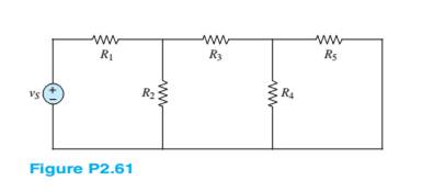
For the circuit shown in Figure P2.61. assume
a. The number of nodes in the circuit.
b. The power delivered by the source
c. The equivalent resistance seen by the source
Want to see the full answer?
Check out a sample textbook solution
Chapter 2 Solutions
Principles and Applications of Electrical Engineering


- Need a aolarrow_forwardNeed correct and step by step handwritten solution. DO NOT USE CHATGPT or other AI tool otherwise downvote and reportarrow_forwardQ1: If the input x[n] = [001111] is applied to a discrete-time LTI system of impulse response h[n] = [321]. Using z-transform, find the output y[n] of the system.arrow_forward
- Q1: If the input x[n] = [001111] is applied to a discrete-time LTI system of impulse response h[n]= = [321]. Find the output y[n] of the system. a. Using analytical technique. b. Using linear convolution technique.arrow_forwardDon't use ai to answer I will report you answerarrow_forwardAn antenna circuit is connected to a 4/4 transmission line with a characteristic impedance 5052. The transmission line is terminated with an antenna having a load impedance Z=60+ j4012. The input voltage at the source is V, 100 V RMS Vy 1. Calculate the input impedance seen by the source at the antenna connection point. 2. Determine the current flowing into the antenna. 3. Verify the supplied power from the source. 4. Calculate the radiated power P 5. Find the power lost in the systemarrow_forward
- A resonant half wavelength dipole is made of copper (G= 5.7 ×10 S/m) wire. Determine the conduction-dielectric (radiation) efficiency e of the dipole antenna, if the operating frequency is = 100 MHz, the radi of the wire b is 3x10²arrow_forward"Detail the solution to the question with an explanation of the integration." A diploe with a total loss resistance of 122, is connected to generator whose internal impedance is 50+j25, the peak voltage of generator is 2 V and the impedance of the dipole excluding the loss resistance is 73+j42.5. All antenna and generator are connected via 50-92 2/4 long lossless transmission line. (a) Draw the equivalent circuit (b) Determine the power supplied by the generator (c) Determine the power radiated by the antennaarrow_forwardFor an X-band (8.2-12.4) GHz rectangular horn antenna with aperture dimensions of 5.5cm and 7.4cm. find its maximum effective aperture (in cm2) when its gain (over isotropic) is 1- 14.8dB at 8.2 GHz 2-16.5dB at 10.3GHz 3- 18dB at 12.4GHzarrow_forward
- Find the directivity in dB and the effective aperture for the following normalized radiation intensity (take f=100 MHz): U(0,0)=0.342csc0 0≤0≤20 20 ≤0≤60 60 ≤0≤18arrow_forwardAn antenna with a radiation impedance of 75+j10 ohm, with 10 ohm loss resistance, is connected to a generator with open-circuit voltage of 12 v and an internal impedance of 20 ohms via a 2/4-long transmission line with characteristic impedance of 75 ohms. (a) Draw the equivalent circuit (b) Determine the power supplied by the generator. (c) Determine the power radiated by the antenna. (d) Determine the reflection coefficient at the antenna terminals.arrow_forwardcircuit analysis using superposition what is value of iarrow_forward
 Introductory Circuit Analysis (13th Edition)Electrical EngineeringISBN:9780133923605Author:Robert L. BoylestadPublisher:PEARSON
 Delmar's Standard Textbook Of ElectricityElectrical EngineeringISBN:9781337900348Author:Stephen L. HermanPublisher:Cengage Learning
 Programmable Logic ControllersElectrical EngineeringISBN:9780073373843Author:Frank D. PetruzellaPublisher:McGraw-Hill Education
 Fundamentals of Electric CircuitsElectrical EngineeringISBN:9780078028229Author:Charles K Alexander, Matthew SadikuPublisher:McGraw-Hill Education
 Electric Circuits. (11th Edition)Electrical EngineeringISBN:9780134746968Author:James W. Nilsson, Susan RiedelPublisher:PEARSON
 Engineering ElectromagneticsElectrical EngineeringISBN:9780078028151Author:Hayt, William H. (william Hart), Jr, BUCK, John A.Publisher:Mcgraw-hill Education,