
Introductory Circuit Analysis (13th Edition)
13th Edition
ISBN: 9780133923605
Author: Robert L. Boylestad
Publisher: PEARSON
expand_more
expand_more
format_list_bulleted
Related questions
Question
thumb_up100%
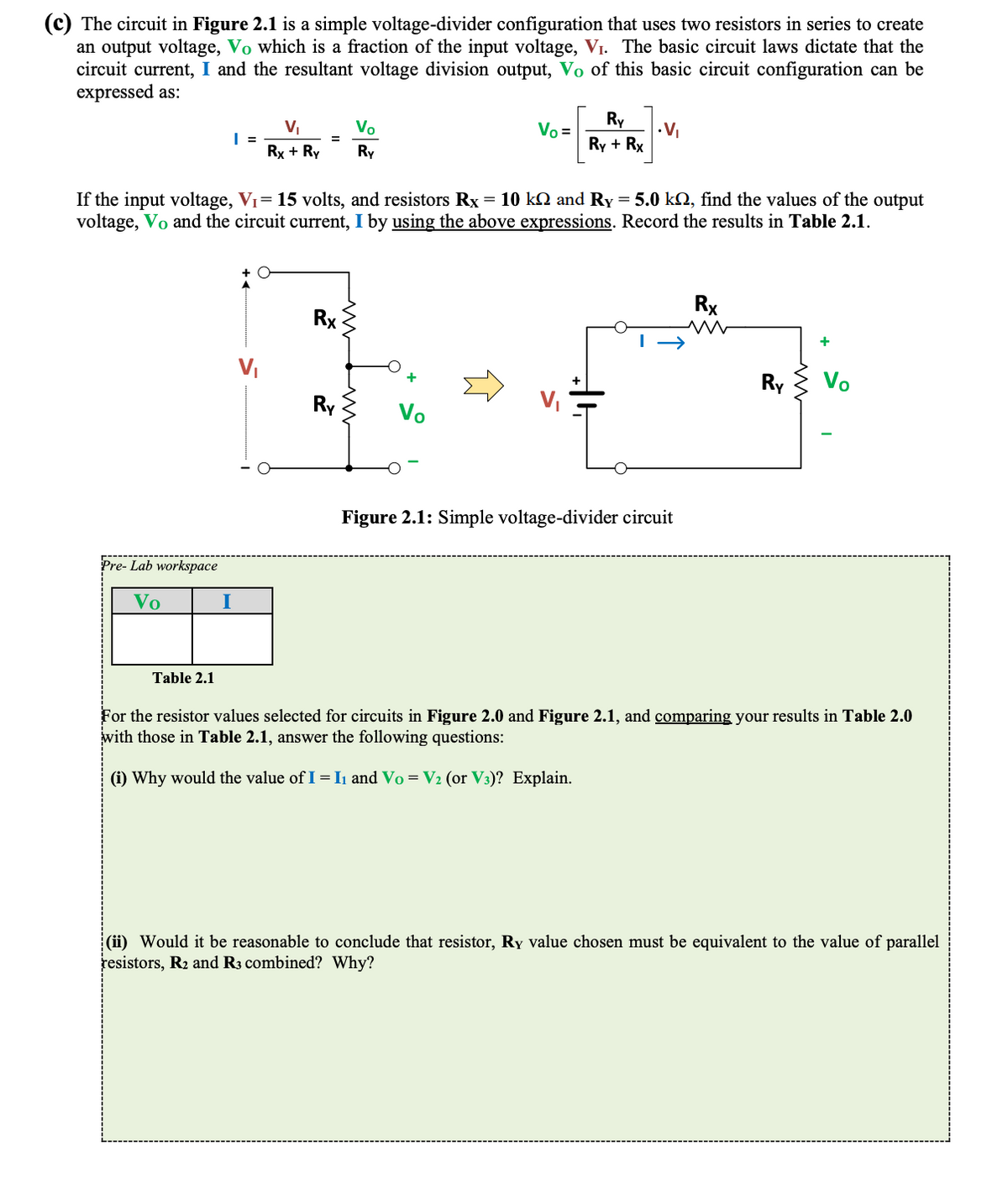

Transcribed Image Text:(c) The circuit in Figure 2.1 is a simple voltage-divider configuration that uses two resistors in series to create
an output voltage, Vo which is a fraction of the input voltage, V₁. The basic circuit laws dictate that the
circuit current, I and the resultant voltage division output, Vo of this basic circuit configuration can be
expressed as:
Pre-Lab workspace
Vo
Table 2.1
| =
I
V₁
Rx + Ry
=
+ O
If the input voltage, V₁= 15 volts, and resistors Rx = 10 k and Ry = 5.0 k, find the values of the output
voltage, Vo and the circuit current, I by using the above expressions. Record the results in Table 2.1.
Rx
Vo
Ry
Ry
Vo =
Vo
Ry
Ry + Rx
.V₁
Figure 2.1: Simple voltage-divider circuit
Rx
Ry
Vo
For the resistor values selected for circuits in Figure 2.0 and Figure 2.1, and comparing your results in Table 2.0
with those in Table 2.1, answer the following questions:
(i) Why would the value of I = I₁ and Vo = V₂ (or V³)? Explain.
(ii) Would it be reasonable to conclude that resistor, Ry value chosen must be equivalent to the value of parallel
resistors, R₂ and R3 combined? Why?

Transcribed Image Text:(b) The simple DC circuit in Figure 2.0 is powered by a 15 volts DC battery input-source (V₁) which will cause
currents to flow through the resistors, R₁, R₂ and R3 as illustrated. When current flows through a resistor, it
creates a voltage across the resistor as governed by the Ohm's Law expression, V = I.R. The Kirchhoff's
Current Law (KCL) states that the sum of all currents entering (or leaving) a node is zero. Therefore, I₁ +
(- 1₂) + (-13) = 0, resulting in I₁ = I₂ + 13.
Even though the basic circuit laws may not be fully covered in class as yet, you may use the above circuit
law expressions to determine the missing values in Table 2.0. Show your analysis on the below workspace
provided. Note: 1 mA = 1x10-³A = 0.001A; and 1 kQ=1x10³Q=1000Q
Pre-Lab workspace
V₁
(15 volts)
V₂
V3
5 volts
←4₂₁₂
Table 2.0
+
I₁
R₁ (10 km)
www
V₁
Figure 2.0: Simple D.C. circuit for voltage and current measurements
R₂
(10 kn)
I₂
0.5 mA
↓
13
+
R3
(10 ΚΩ)
What relationship exists between voltages V₂ and V3? and between currents, I2 and 13? Why?
Was the voltage relationship V₁ = V₁ + (V₂ or V3) established? If so, why would it be the case?
If the resistor, R₁ is replaced with a wire (i.e. make R₁ = 0 22), intuitively what might the resultant value of the
voltage, V3 be? Explain.
Expert Solution
This question has been solved!
Explore an expertly crafted, step-by-step solution for a thorough understanding of key concepts.

This is a popular solution

Trending nowThis is a popular solution!

Step by stepSolved in 3 steps with 3 images

Knowledge Booster


Learn more about
Need a deep-dive on the concept behind this application? Look no further. Learn more about this topic, electrical-engineering and related others by exploring similar questions and additional content below.Similar questions
- How do I do number 1arrow_forwardFor given value of the circuit, Vsupply = 120 V, and with R₁= 2002, R₂=30.0, R3=75, R4=30N, R5= 200, R6-400 and R7=12002? • What is the voltage drop across Ro? 1. a) 32 V b) 48V c) 100V d) 120V 2. 48 Volts 100 Volts 32 Volts 120 Volts V1 120 V R1 ww 2002 R3 750 R7 12002 R6 m 40Q R2 2300 R4 30Q R5 2200arrow_forwardHelp me answer, I want to check my solution To get the contribution of the 75V source to iR, we first kill the 50mA source. What is the resulting equivalent resistance in series with the 75K resistor (in Kohms) To get the contribution of the 75V source to iR, we first kill the 50mA source. What is the resulting value of iR (in mA)? What is the nodal equation for Vx? What is the Thevanin voltage in (Volts) and Thevanin resistance in (Kohms)?arrow_forward
- c) Using minimum number of components, design a voltage divider which can deliver 1 W at 100V, 2W at -50V and 1.6W at -80V. The voltage source has an internal resistance of 200 Q and supplies a current of 100mA. What is the open - circuit voltage of the voltage source? All resistance in ohm.arrow_forwardIn the circuit below, the currents through the four resistors are as indicated. Use the junction rule to write the equations representing the relationship between the currents at the point d. (Use the following as necessary: 14, 15, and 16.) 16=14+15 X = 0 &₁ 15 R4 d E₂ =&arrow_forwardThe images are attached with the question and circuit. Please include a drawing with the solution. Thank youarrow_forward
- V1 R1 V2 Da Db R2 www V3 Given that R1=2k, R2=1k, and Da and Db are Si Diodes: a. What is V3 in terms of V1 when Da is ON? b. What is V3 in terms of V1 when Db is ON? c. What is V3 in terms of V1 when Da and Db is OFF?arrow_forwardA p-n heterojunction is formed though Semiconductor A intimately contacting with Semiconductor B. The energy band diagrams for two semiconductors are shown in Figure 2 on page 4. It is given that = ХА — 2.0 еV, хв — 1.5 eV, EрА %3D 2.9eV, Erв %3D 2.0 еV, EgA 3D 1.3 eV, Egв — 2.8 eV If a small positive voltage is applied to Semiconductor A, and Semiconductor B is grounded, explain how the potential barrier changes in comparison with the thermal equilibrium condition. The vacuum level Хв ХА Есв ECA- EFB EgB EFA EVA EVB Semiconductor A Semiconductor Barrow_forward
arrow_back_ios
arrow_forward_ios
Recommended textbooks for you
- Introductory Circuit Analysis (13th Edition)Electrical EngineeringISBN:9780133923605Author:Robert L. BoylestadPublisher:PEARSON
 Delmar's Standard Textbook Of ElectricityElectrical EngineeringISBN:9781337900348Author:Stephen L. HermanPublisher:Cengage Learning
 Programmable Logic ControllersElectrical EngineeringISBN:9780073373843Author:Frank D. PetruzellaPublisher:McGraw-Hill Education
  Fundamentals of Electric CircuitsElectrical EngineeringISBN:9780078028229Author:Charles K Alexander, Matthew SadikuPublisher:McGraw-Hill Education
 Electric Circuits. (11th Edition)Electrical EngineeringISBN:9780134746968Author:James W. Nilsson, Susan RiedelPublisher:PEARSON
 Engineering ElectromagneticsElectrical EngineeringISBN:9780078028151Author:Hayt, William H. (william Hart), Jr, BUCK, John A.Publisher:Mcgraw-hill Education,
Introductory Circuit Analysis (13th Edition)
Electrical Engineering
ISBN:9780133923605
Author:Robert L. Boylestad
Publisher:PEARSON
Delmar's Standard Textbook Of Electricity
Electrical Engineering
ISBN:9781337900348
Author:Stephen L. Herman
Publisher:Cengage Learning
Programmable Logic Controllers
Electrical Engineering
ISBN:9780073373843
Author:Frank D. Petruzella
Publisher:McGraw-Hill Education
Fundamentals of Electric Circuits
Electrical Engineering
ISBN:9780078028229
Author:Charles K Alexander, Matthew Sadiku
Publisher:McGraw-Hill Education
Electric Circuits. (11th Edition)
Electrical Engineering
ISBN:9780134746968
Author:James W. Nilsson, Susan Riedel
Publisher:PEARSON
Engineering Electromagnetics
Electrical Engineering
ISBN:9780078028151
Author:Hayt, William H. (william Hart), Jr, BUCK, John A.
Publisher:Mcgraw-hill Education,