
Introductory Circuit Analysis (13th Edition)
13th Edition
ISBN: 9780133923605
Author: Robert L. Boylestad
Publisher: PEARSON
expand_more
expand_more
format_list_bulleted
Related questions
Concept explainers
Question
For the circuit shown in Figure P1.77, solve for the current i x. What types of sources are
present in this circuit?
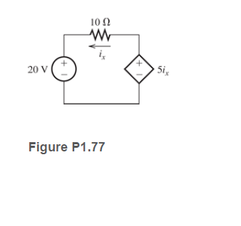

Transcribed Image Text:10 2
20 V
Si
Figure P1.77
Expert Solution
This question has been solved!
Explore an expertly crafted, step-by-step solution for a thorough understanding of key concepts.

This is a popular solution

Trending nowThis is a popular solution!

Step by stepSolved in 2 steps with 2 images

Knowledge Booster


Learn more about
Need a deep-dive on the concept behind this application? Look no further. Learn more about this topic, electrical-engineering and related others by exploring similar questions and additional content below.Similar questions
- A variable resistor enables one to change the resistance. One design involves a horizontal tube of wire with a slider on the top. By moving the slider, one can change the length of wire involved, thus changing the resistance. Imagine a tube of wire with one layer made from wire 1.00 mm in diameter wrapped in a single layer with no gaps between the loops of wire ( the wire looks like a solid layer down the length of the tube). The radius of the tube is 2.50 cm. Moving the slider 1.00 cm changes the resistance of the variable resistor by 3.00 Ohms. What is the resistivity of the wire, and what is it made of?arrow_forwardcan someone show me how to do this problem and explain the answer step by steparrow_forward(a) defibrillator sends a 6 A current through the chest of a patient by applying a 11000 V potential as in the figure. What is the resistance of the path (through the wire and the body)? -aira R= (b) The defibrillator paddles make contact with the patient through a conducting gel that greatly reduces the path resistance. To understand the importance of using the gel, discuss the difficulties that would ensue if a larger voltage were used to produce the same current through the patient, but with the path having perhaps 50 times the resistance by finding the ratio, P no-gel P gel e- ΚΩ (Hint: The current must be about the same, so a higher voltage would imply greater power. Use this equation for power: P = PR.) What difficulties arise when no gel is used? a. The voltage is too high for the human body even when the current is the same. b. There is a risk of skin burns because of the high power deposited.arrow_forward
- Okay for Determine the mathematical expression for the voltage vC and the current iC for the discharge phase. I got Vc = 8e-t/0.2s V and iC = -4e-t/0.2mA But I need help with the last question Plot the waveforms of vC and iC for a period of time extending from 0to 2 s from when the switch was thrown into position 1.arrow_forward.1.1 . Describe the theoretical underpinnings of superconductivity and its potential applications in electrical engineering, highlighting the challenges associated with achieving practical superconducting devices. don't use Al solution either dislikearrow_forward1.4 The charge cycle shown in Figure PL4 is an example of a three-rate charge. The current is held constant at 30 mA for 6 h. Then it is switched to 20 mA for the next 3 h. Find: a. The total charge transferred to the battery. b. The energy transferred to the battery.Page 58 Hint: Recall that energy w is the integral of power, or P = dw/dr. 1.7 V 1.2 V 9.6V 05 V 30 mA 20 mA Figure P14 3h 3h 6h 6h 9h 7arrow_forward
- 2.43 Suppose a 12-V voltage source is connected between nodes A and B of the circuit of Figure P2.14, with the posi- tive side at A. Find the magnitude and polarity of the voltage appearing between C and D, as well as the power supplied by the source.arrow_forwardSolving #15, I do not understand how to calculate Vtharrow_forwardYou have developed an idea for using a poly Si surface‐ micromachined cantilever. Initially, you designed a process flow for creating this simple structure, and the process flow is detailed in the figure below. ( cross section view and top view)There are several critical errors with this process (things that won’t work or won’t produce the result). Please find the critical errors in this process flow and, where possible, suggest alternate approaches. Do not worry about the accumulation of errors, but rather treat each step assuming that the structure up to that step could be created.This structure is actually quite simple to make. Develop a simpler process flow and associated masks to create the final structure. Be sure to show cross‐sectional and planar views of all key steps in the process.arrow_forward
- THE POLARITY MARKINGS ON TWO WINDINGS MUST BE DETERMINED EXPERIMENTALLY. THE DEVICE FOR SUCH DETERMINATION IS SHOWN IN THE FIGURE BELOW. THAT THE TERMINAL CONNECTED TO THE POSITIVE TERMINAL OF THE BATTERY RESERVES THE POLARITY MARKING AS SHOWN IN THE FIGURE. WHEN THE SWITCH IS OPEN, THE DC VOLTMETER UNDERGOES A NEGATIVE DEFLECTION. WHERE ON THE CONNECTED WINDING SHOULD A POLARITY MARKING BE ATTACHED TO THE VOLTMETER? t = 0 R )cc VOLTIMETER VB- CHOOSE AN OPTION BELOW: A. POINT AT THE LOWER END OF THE INDUCTOR B. POINT AT THE TOP END OF THE INDUCTOR C. NONE OF THE OPTIONS D. A DOT AT THE TOP END AND BOTTOM END C E. THERE IS NO COUPLING BETWEEN THE INDUCTORS, SO IT IS NOT NECESSARY TO PLACE A DOTarrow_forwardElectrical Engineering - elctronic Please solve the question quicklyarrow_forward1. Passive voltage response to injected current step is not instantaneous, why not? Key words: time constant, resistance/capacitance propertiesarrow_forward
arrow_back_ios
SEE MORE QUESTIONS
arrow_forward_ios
Recommended textbooks for you
- Introductory Circuit Analysis (13th Edition)Electrical EngineeringISBN:9780133923605Author:Robert L. BoylestadPublisher:PEARSON
 Delmar's Standard Textbook Of ElectricityElectrical EngineeringISBN:9781337900348Author:Stephen L. HermanPublisher:Cengage Learning
 Programmable Logic ControllersElectrical EngineeringISBN:9780073373843Author:Frank D. PetruzellaPublisher:McGraw-Hill Education
  Fundamentals of Electric CircuitsElectrical EngineeringISBN:9780078028229Author:Charles K Alexander, Matthew SadikuPublisher:McGraw-Hill Education
 Electric Circuits. (11th Edition)Electrical EngineeringISBN:9780134746968Author:James W. Nilsson, Susan RiedelPublisher:PEARSON
 Engineering ElectromagneticsElectrical EngineeringISBN:9780078028151Author:Hayt, William H. (william Hart), Jr, BUCK, John A.Publisher:Mcgraw-hill Education,
Introductory Circuit Analysis (13th Edition)
Electrical Engineering
ISBN:9780133923605
Author:Robert L. Boylestad
Publisher:PEARSON
Delmar's Standard Textbook Of Electricity
Electrical Engineering
ISBN:9781337900348
Author:Stephen L. Herman
Publisher:Cengage Learning
Programmable Logic Controllers
Electrical Engineering
ISBN:9780073373843
Author:Frank D. Petruzella
Publisher:McGraw-Hill Education
Fundamentals of Electric Circuits
Electrical Engineering
ISBN:9780078028229
Author:Charles K Alexander, Matthew Sadiku
Publisher:McGraw-Hill Education
Electric Circuits. (11th Edition)
Electrical Engineering
ISBN:9780134746968
Author:James W. Nilsson, Susan Riedel
Publisher:PEARSON
Engineering Electromagnetics
Electrical Engineering
ISBN:9780078028151
Author:Hayt, William H. (william Hart), Jr, BUCK, John A.
Publisher:Mcgraw-hill Education,