
Concept explainers
Videos
Suppose the current through a wire is given by the curve shown in Figure P2.9.
a. Find the amount of charge q that flows through the wire between
b. Repeatpartafor
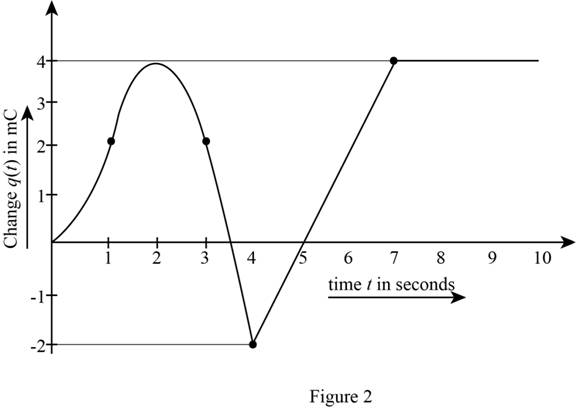
c. Sketch
(a)
The amount of current that flows through the wire for the given time.
Answer to Problem 2.9HP
The current that flows though the wire for the time interval
Explanation of Solution
Calculation:
The given time is
The conversion from
The conversion from
The conversion from
The conversion from
The given diagram is shown in Figure 1.
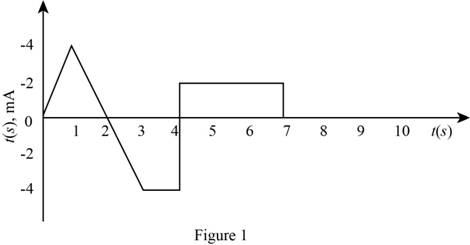
The expression for the current as a function of time is given by,
The slope of the line that represents the current from
The current for the time interval
The expression for the charge that flows through the wire for the time interval
Substitute
Conclusion:
Therefore, the charge that flows though the wire for the time interval
(b)
The charge that flows through the given time interval.
Answer to Problem 2.9HP
The charge that will flow through the wire form
Explanation of Solution
Calculation:
The given time interval is
The slope of the line that represents the current from
The conversion of
The conversion of
The conversion of
The current for the time interval
Substitute
Substitute
The expression for the charge stored from
Substitute
Substitute
Solve further as,
The expression for the charge stored from
Substitute
Substitute
Solve further as,
The mathematical expression for the straight line that represents the current waveform from
The expression for the charge stored from
Substitute
Solve further as,
The mathematical expression for the straight line that represents the current waveform from
The expression for the charge stored from
Substitute
The mathematical expression for the straight line that represents the current waveform from
The expression for the charge stored from
Substitute
The mathematical expression for the straight line that represents the current waveform from
The expression for the charge stored from
Substitute
The current is zero for
The expression for the charge stored from
Substitute
The charge stored from
Substitute
The charge stored from
Substitute
Conclusion:
Therefore, the charge that will flow through the wire form
(c)
To sketch:
The graph for
Answer to Problem 2.9HP
The sketch for
Explanation of Solution
Calculation:
The expression for the current for different time interval is given by,
The integration of the above equation with respect to time to obtain the charge expression is given by,
The evaluated form for the expression of charge for the different time interval is given by,
Substitute
Substitute
Substitute
Substitute
Substitute
Substitute
Substitute
Substitute
Substitute
Substitute
Substitute
The sketch of
The required diagram is shown in Figure 2.
Want to see more full solutions like this?
Chapter 2 Solutions
Principles and Applications of Electrical Engineering


- lell L1 R Ro 2. In this figure, assume arbitrary numbers for R1, R2, L1, and L2 including some number for the battery E. Find the rate of current in which inductor one (L1) is changing just after the switch is closed. Next, find the current in L1 after some time after the switch has been closed. lellarrow_forwardA coil has a resistance of 18 when it mean temp is from 20o C to 50o C. Find its mean temp rise when its resistance is 21 and the surrounding temp is 15o C. A potential difference of 250 V is applied to a copper field coil at a temp of 15o C and the current is 5A. What will be the mean temp of the coil when the current has fallen to 3.91 A, the applied voltage being the same as before.arrow_forward(b) The simple DC circuit in Figure 2.0 is powered by a 15 volts DC battery input-source (V₁) which will cause currents to flow through the resistors, R₁, R₂ and R3 as illustrated. When current flows through a resistor, it creates a voltage across the resistor as governed by the Ohm's Law expression, V = I.R. The Kirchhoff's Current Law (KCL) states that the sum of all currents entering (or leaving) a node is zero. Therefore, I₁ + (- 1₂) + (-13) = 0, resulting in I₁ = I₂ + 13. Even though the basic circuit laws may not be fully covered in class as yet, you may use the above circuit law expressions to determine the missing values in Table 2.0. Show your analysis on the below workspace provided. Note: 1 mA = 1x10-³A = 0.001A; and 1 kQ=1x10³Q=1000Q Pre-Lab workspace V₁ (15 volts) V₂ V3 5 volts ←4₂₁₂ Table 2.0 + I₁ R₁ (10 km) www V₁ Figure 2.0: Simple D.C. circuit for voltage and current measurements R₂ (10 kn) I₂ 0.5 mA ↓ 13 + R3 (10 ΚΩ) What relationship exists between voltages V₂ and…arrow_forward
- For the circuit given in Figure-2, let the switch was initially closed at position-1 for a 5T time and then the switch is moved to position-2 and left there. Determine: i. Draw capacitor charging circuit and time constant for charging circuit. ii. Expression for vc and ic while switch is in position-1. iii. Compute vc and ic at t = 1T time while switch is at position-1. iv. Time constant for discharging circuit and draw discharging circuit. v. Expression for vc and ic while switch is at position-2. vi. Compute vc and ic at t = 1T while switch is at position-2. vii. Sketch the voltage and current plot for charging and discharging of capacitor and indicate voltage and currents points on the plot. 10 kΩ ( 15 kN R1 R3 E R2 5 kN E= 200V Figure-2 C= 20.75miyu Farrow_forwarda) A coil consist of 2000 turns of copper wire having a cross sectional area of 0.8mm?. The mean length per turn is 80 cm and the resistivity of copper is 0.02µN-m. Find the resistance of the coil and power absorbed by the coil when connected across 110V D.C supply.arrow_forwardIn the figure given we have u(t)=10- cosot [V]. We assume the diodes and the A-meter (A) to be ideal. a) Plot the waveform of the current flowing through the A-m in scale. b) What is the reading of the A-m, if it is moving-coil type? A u(t) R1 R2 c) What is the reading of the A-m, if it is moving-iron type? d) Calculate the power factor of the WHOLE structure. 5Ω 10Ωarrow_forward
- Q.basic electrical engineering.arrow_forwardConsider the circuit shown in figure 2-8. the circuit operates at 60 hz, the rms of the voltage is 120 volts, the resistor has a value of 40 ohm, the inductor is 0.1592 H, and the capacitance is 33.16 UF. a) Find the impedance of the inductor and the capacitor. b) Find the current in each leg of the circuit and the total current from the source. c) Draw a phasor diagram showing the source voltage and all the currents. d) Find the total impedance of the RLC parallel combinationarrow_forward2. A charge will experience a force in an electric field when it is: .............a. Stationaryb. Movingc. Stationary Or movingd. None of above3. The algebraic sum of voltages around any closed path in a network is equal to ..........a. Infinityb. 1c. 0d. Negative polarity4. A junction connects two (or) more than two network elements meet known as a ..........a. Nodeb. Branchc. Loopd. Mesh Final Research Project 7 | P a g e5. With Ohm's law, if voltage increases and resistance stays the same:..................a. current remains the sameb. power decreasesc. current increasesd. resistance decreases6. In superconductivity the conductivity of a material becomes .....................a. Zerob. Finitec. Infinited. None of the above7. If a negative charge move to a positivearrow_forward
- Question 2 The resistance of semiconductor thermistor is given by: R(T)=R0.exp B P[B(+=+=+)] T To The resistance at 273 K is 1 k, and at 373 K is 100 kQ. Find the resistance at 313 K.arrow_forward9 The point form of Ohm's Law is the basis for: (The answer cannot be found on the other choices.) Kirchhoff's current law; the heating effect of resistors; the electron flow of current;arrow_forwardWhen subjected to pressure, certain materials create a relatively small voltage. Materials that behave in this manner are called piezoelectrics. Investigate the applications in which piezoelectrics are used. Write a brief report discussing your findings.arrow_forward
 Introductory Circuit Analysis (13th Edition)Electrical EngineeringISBN:9780133923605Author:Robert L. BoylestadPublisher:PEARSON
 Delmar's Standard Textbook Of ElectricityElectrical EngineeringISBN:9781337900348Author:Stephen L. HermanPublisher:Cengage Learning
 Programmable Logic ControllersElectrical EngineeringISBN:9780073373843Author:Frank D. PetruzellaPublisher:McGraw-Hill Education
 Fundamentals of Electric CircuitsElectrical EngineeringISBN:9780078028229Author:Charles K Alexander, Matthew SadikuPublisher:McGraw-Hill Education
 Electric Circuits. (11th Edition)Electrical EngineeringISBN:9780134746968Author:James W. Nilsson, Susan RiedelPublisher:PEARSON
 Engineering ElectromagneticsElectrical EngineeringISBN:9780078028151Author:Hayt, William H. (william Hart), Jr, BUCK, John A.Publisher:Mcgraw-hill Education,