
Principles and Applications of Electrical Engineering
6th Edition
ISBN: 9780073529592
Author: Giorgio Rizzoni Professor of Mechanical Engineering, James A. Kearns Dr.
Publisher: McGraw-Hill Education
expand_more
expand_more
format_list_bulleted
Concept explainers
Videos
Textbook Question
Chapter 2, Problem 2.10HP
The charge cycle shown in Figure P2.10 is anexample of a two-rate charge. The current is heldconstant at 70 mA for 1 h. Then it is switched to 60 mA for the next 1 h. Find:
a. The total charge transferred to the battery.
b. The total energy transferred to the battery.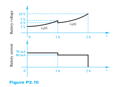
Expert Solution & Answer
Want to see the full answer?
Check out a sample textbook solution
Students have asked these similar questions
Consider the circuit in figure 2. Diode D1 is germanium and D2 is gallium arsenide. Determine the following:
a. The states of D1 and D2. Explain.
b. Current I1 through R1
c. Current I2 through R2
d. Current I3 through R3
e. Voltage across R1
f. Voltage across R2
g. Voltage Across R3
Calculate the equivalent resistances Rin of the following circuits. (The resistance value of the diodes in the conduction will be 0, the resistance value of the diodes in the insulation will be taken as infinity. R1=10ohm
1%AE I. ln.
A:00
Bgåno - (3) ruall
(2-6) A half-wave rectifier circuit with a diode resistance equal to 1IKN is shown in Figure (2-
72) this circuit is used to supply power of 200 sin t t to 10 kn load.
Determine 1) the maximum load current. 2) the mean load current 3)the ms alternating load
current.
4) the DC power supplied to the load. 5) the input power to the anode circuit.
6) the rectification efficiency. 7) the percentage of regulation. 8) the ripple current.
R=10°0
V,
AC O
R=10°Q
Figure (2-72) the circuit of problem (2-6).
II
Chapter 2 Solutions
Principles and Applications of Electrical Engineering
Ch. 2 - A free electron has an initial potential energy...Ch. 2 - The units for voltage, current, and resistance are...Ch. 2 - A particular fully charged battery can deliver...Ch. 2 - The charge cycle shown in Figure P2.4 is an...Ch. 2 - Batteries (e.g., lead-acid batteries) store...Ch. 2 - What determines: a. The current through an ideal...Ch. 2 - An automotive battery is rated at 120 A-h. This...Ch. 2 - A car battery kept in storage in the basement...Ch. 2 - Suppose the current through a wire is given by the...Ch. 2 - The charge cycle shown in Figure P2.10 is...
Ch. 2 - The charging scheme used in Figure P2.11 is...Ch. 2 - The charging scheme used in Figure P2.12 is...Ch. 2 - Use KCL to determine the unknown currents in the...Ch. 2 - Use KCL to find the current i1 and i2 in Figure...Ch. 2 - Use KCL to find the current i1,i2, and i3 in the...Ch. 2 - Use KVL to find the voltages v1,v2, and v3 in...Ch. 2 - Use KCL to determine the current i1,i2,i3, and i4...Ch. 2 - In the circuits of Figure P2.18, the directions...Ch. 2 - Find the power delivered by each source in Figure...Ch. 2 - Determine whether each element in Figure P2.20 is...Ch. 2 - In the circuit of Figure P2.21, determine the...Ch. 2 - For the circuit shown in Figure P2.22: a....Ch. 2 - For the circuit shown in Figure P2.23,...Ch. 2 - For the circuit shown in Figure P2.24, determine...Ch. 2 - For the circuit shown in Figure P2.25, determine...Ch. 2 - Prob. 2.26HPCh. 2 - Prob. 2.27HPCh. 2 - Prob. 2.28HPCh. 2 - Prob. 2.29HPCh. 2 - Prob. 2.30HPCh. 2 - Prob. 2.31HPCh. 2 - In the circuit of Figure P2.32, assume v2=vs/6 and...Ch. 2 - Prob. 2.33HPCh. 2 - An incandescent light bulb rated at 100 W will...Ch. 2 - An incandescent lightbulb rated at 60 W...Ch. 2 - Refer to Figure P2.36, and assume that...Ch. 2 - Refer to Figure P2.37, and assume that...Ch. 2 - Refer to Figure P2.38, and assume...Ch. 2 - Prob. 2.39HPCh. 2 - With no load attached, the voltage at the...Ch. 2 - Prob. 2.41HPCh. 2 - For the circuits of Figure P2.42, determine the...Ch. 2 - At an engineering site, a 1-hp motor is placed...Ch. 2 - Cheap resistors are fabricated by depositing a...Ch. 2 - Prob. 2.45HPCh. 2 - Use KCL and Ohm’s law to determine the current...Ch. 2 - Refer to Figure P2.13. Assume R0=1,R1=2,R2=3,R3=4...Ch. 2 - Apply KCL and Ohm’s law to find the power supplied...Ch. 2 - Refer to Figure P2.49 and assume...Ch. 2 - Refer to Figure P2.49 and assume...Ch. 2 - Prob. 2.51HPCh. 2 - The voltage divider network of Figure P2.52 is...Ch. 2 - Find the equivalent resistance seen by the source...Ch. 2 - Find the equivalent resistance seen by the source...Ch. 2 - In the circuit of Figure P2.55, the power absorbed...Ch. 2 - Find the equivalent resistance between terminals...Ch. 2 - For the circuit shown in Figure P2.57, find the...Ch. 2 - For the circuit shown in Figure P2.58,find the...Ch. 2 - Refer to Figure P2.59. Assume...Ch. 2 - Find the equivalent resistance seen by the source...Ch. 2 - For the circuit shown in Figure P2.61. assume...Ch. 2 - Determine the equivalent resistance of the...Ch. 2 - For the circuit shown in Figure P2.58, assume...Ch. 2 - In the circuit of Figure P2.64, find the...Ch. 2 - Refer to Figure P2.64 and determine the equivalent...Ch. 2 - Find the equivalent resistance seen by the source...Ch. 2 - Determine the voltage vo between nodes A and Bin...Ch. 2 - Refer to Figure P2.68 and assume...Ch. 2 - Prob. 2.69HPCh. 2 - Prob. 2.70HPCh. 2 - Prob. 2.71HPCh. 2 - The circuit of Figure P2.72 is used to measure the...Ch. 2 - Consider the practical ammeter, depicted in Figure...Ch. 2 - Prob. 2.74HPCh. 2 - Prob. 2.75HPCh. 2 - Prob. 2.76HPCh. 2 - A voltmeter is used to determine the voltage...Ch. 2 - Prob. 2.78HPCh. 2 - Figure P2.79 shows an aluminum cantilevered beam...Ch. 2 - Refer to Figure P2.79 but assume that the...
Knowledge Booster


Learn more about
Need a deep-dive on the concept behind this application? Look no further. Learn more about this topic, electrical-engineering and related others by exploring similar questions and additional content below.Similar questions
- In the circuit shown in Figure 2–41 (p. 94), the current I is 34.28 mA. What is the voltage drop across the diode? What is its dc resistance?arrow_forwardThe charge cycle shown in Figure is an exampleof a two-rate charge. The current is held constant at50 mA for 5 h. Then it is switched to 20 mA for thenext 5 h. Find: a. The total charge transferred to the battery.b. The energy transferred to the battery.arrow_forwardThe half-wave rectifier in Figure 2–19 has a 250-μF filter capacitor and a 1.5-kOhm load. The ac source is 120 V rms with frequency 60 Hz. The voltage drop across the silicon diode is 0.7V. Assuming light loading, find (a) the dc value of the load voltage; (b) the peak-to-peak value of the ripple (c) the %-ripple (d) plot vin(t), vR(t) (output without the filter cap) and vL(t) (output with the filter cap) all on the same grapharrow_forward
- a. If you do not go completely around the loop when applying Kirchhoff’s voltage law, then the algebraic sum of the voltages cannot be determined the algebraic sum of the voltages will always be positive the algebraic sum of the voltages will always be negative the algebraic sum is the voltage between the start and finish points b. A p -type semiconductor is a semiconductor doped with impurity atoms whose electron valence is +4 pentavalent impurity atoms trivalent impurity atomsarrow_forwardFind the current through the diode in the circuit shown. Assume the diode to be ideal. 50 92 www R₁ D V= 10 V = O 185 mA O 46 mA O 140 mA O 28 MA 592 wwww R₂ Barrow_forward1) It can be accepted that D1 and D2 diodes are from the same family in the circuit given in the figure. a) output voltage, wwwiwwwww wwwww wwwwwwwwwwn w www w 0.33 k2 wwwwww wwwww E 10 V D Si D, Si b) the current flowing through the resistor, ww ww c) currents flowing through the diodes గ wl ww ww calculate. www ww +arrow_forward
- Please answer both question or give someone else to answer. Need small explanations. Which of the following are the majority carriers in p-type semiconductors? a. electrons b. photons c. holes d. neutrons Two capacitors C1 = 1.5 μF and C2 = 5 μF are in series. If the charge stored by C1 is 10 C, determine the charge stored by C2. a. 3 C b. 10 C c. 1.5 C d. 4 Carrow_forwardc) Calculate the current through a 50 2 resistor in the circuit shown in the below figure. Assume the diodes to be of silicon and the forward resistance of each diode is r=1 2. Show the answer steps. D. D2 50 2 ww 20 V= D4 D3arrow_forwardFor the circuit shown in figure 1, the diodes is in complete model and the resistance of both diodes are 5 Ohm. Find the current in the resistance RL. When the both switch S1 and switch S2 are ON. v1= 6V, V3 =3 Vv2=12 V.arrow_forward
- D. , D2 A R2 200 Q 100HZ C1 R1 R3 D4 D3 8 µF 2 kQ 3 kQ D Answer the following questions, since the minimum voltage value to transmit the zener diode in the figure given above is 9V and the power of this Zener diode is 0.3 watts. a) Enter the name of the circuit in the figure. b) What are the diodes/diodes in positive half-loop transmission?arrow_forwardDetermine the minimum and the maximum load currents for which the zener diode in Figure 2–14 will maintain regulation. What is the minimum value of R1 that can be used? Vz. = 12 V, IzK = 1 mA, and I7M = 50 mA. Assume an ideal zener diode where Zz = 02 and Vz remains a constant 12 V over the range of current values, for simplicity. R IT 470 2 VIN R 24 V Figure 2-14arrow_forwardlell L1 R Ro 2. In this figure, assume arbitrary numbers for R1, R2, L1, and L2 including some number for the battery E. Find the rate of current in which inductor one (L1) is changing just after the switch is closed. Next, find the current in L1 after some time after the switch has been closed. lellarrow_forward
arrow_back_ios
SEE MORE QUESTIONS
arrow_forward_ios
Recommended textbooks for you
 Introductory Circuit Analysis (13th Edition)Electrical EngineeringISBN:9780133923605Author:Robert L. BoylestadPublisher:PEARSON
 Delmar's Standard Textbook Of ElectricityElectrical EngineeringISBN:9781337900348Author:Stephen L. HermanPublisher:Cengage Learning
 Programmable Logic ControllersElectrical EngineeringISBN:9780073373843Author:Frank D. PetruzellaPublisher:McGraw-Hill Education
 Fundamentals of Electric CircuitsElectrical EngineeringISBN:9780078028229Author:Charles K Alexander, Matthew SadikuPublisher:McGraw-Hill Education
 Electric Circuits. (11th Edition)Electrical EngineeringISBN:9780134746968Author:James W. Nilsson, Susan RiedelPublisher:PEARSON
 Engineering ElectromagneticsElectrical EngineeringISBN:9780078028151Author:Hayt, William H. (william Hart), Jr, BUCK, John A.Publisher:Mcgraw-hill Education,
Introductory Circuit Analysis (13th Edition)
Electrical Engineering
ISBN:9780133923605
Author:Robert L. Boylestad
Publisher:PEARSON
Delmar's Standard Textbook Of Electricity
Electrical Engineering
ISBN:9781337900348
Author:Stephen L. Herman
Publisher:Cengage Learning
Programmable Logic Controllers
Electrical Engineering
ISBN:9780073373843
Author:Frank D. Petruzella
Publisher:McGraw-Hill Education
Fundamentals of Electric Circuits
Electrical Engineering
ISBN:9780078028229
Author:Charles K Alexander, Matthew Sadiku
Publisher:McGraw-Hill Education
Electric Circuits. (11th Edition)
Electrical Engineering
ISBN:9780134746968
Author:James W. Nilsson, Susan Riedel
Publisher:PEARSON
Engineering Electromagnetics
Electrical Engineering
ISBN:9780078028151
Author:Hayt, William H. (william Hart), Jr, BUCK, John A.
Publisher:Mcgraw-hill Education,
How does an Alternator Work ?; Author: Lesics;https://www.youtube.com/watch?v=tiKH48EMgKE;License: Standard Youtube License