
Videos
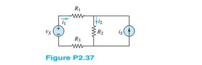
Refer to Figure P2.37, and assume that
a. The current
b. The power supplied by the source
Want to see the full answer?
Check out a sample textbook solution
Chapter 2 Solutions
Principles and Applications of Electrical Engineering


- Consider the circuit shown in the figure below. (Let R₁ = 6.00 0, R₂ = 8.00 0, and 8 - 10.0 V.) 2.000 W 10.00 www 5.000 www & 16 (a) Find the voltage across R₁. (b) Find the current in R₁. R₂ wwwarrow_forwardConsider the circuit of resistors shown. Find the equivalent resistance Reg • Find the currents ,...,Is through each resistor and the voltages V1,..,Vs across each resistm Find the total power P dissipated in the circuit. R = 62 R:= 42 R=122 R = 392 R=52 E=12Varrow_forwardP2.70. Solve for the power delivered by the volt- age source in Figure P2.70, using the mesh- current method. 592 WWW M 792 i₁ 192 ww iz 1+ 62 V Figure P2.70 M 1192 iz •3Ωarrow_forward
- a. Thévenin's and Norton's theorem are two examples of circuit theorem. With the help of equivalent circuits, distinguish the difference between them.arrow_forwardThe circuit shown below is an example of a simple voltage regulator. Determine the current through R2 in mA. Assume the following values for the resistors: R1 = 13 kn, R2 = 10 kn. Express your answer using three decimal places. Assume the opamp is ideal and Q1's B is infinity. Q1 VCC Vref NPN U1 OUT 20V 1.2V R1 R2 + +arrow_forwardRefer to the figure. Given 2RR R2 = 3R2 - RL a) Design the power supply circuit so that y = 3v,when R,-600 Q. by Assume input voltage is 180 V. Which resistor in the circuit dissipates the most power? What is the power? c) Which resistor dissipates the least power? What is the power? R2 ww R ww I RL 14. ww- 年 wwarrow_forward
- Differentiate between Kirchhoff's Voltage Law and Kirchhoff's Current Law. Support you answer by appropriate example. Debate that how these laws are supportive to solve complex circuits.arrow_forwardFinding the direction of the currents. Finding currents given that R2: 10.94 x 10^2 ohmR3: 9.89 x 10^2 ohmR4: 25 ohm Terminal Potential: Battery 1: 5 V using Kirchoff's laws. You will check some of the laws that govern electrical circuitsDirect current: conservation of current in a node, addition of potentialsfor series components, addition of currents for parallel componentsarrow_forwardP2J A resistance Ri of. 5kr is shunted by a Conductance Gof Soy5. The combinatoin draws a current of Lo MA from a dc. supply..Calculates a) GT and RT b) I, and Iz ) The Voltage acvoss each resistor and the Suypply. Yoltage. LAnse a-250y S+4*2 b-8mA ,2 mA Catorarrow_forward
- Q1. For the circuit in the figure, using Kirchoff's rules, (a) Calculate the currents 1₁, 12 and 13 in the three branches. (b) What is the change in potential V₁ - V₁ =? 30 www 12 V 20 20 www 502 wi 30 13 V Barrow_forwardQ2(a) For the circuit shown in Figure Q2 (a), find Vo and the power by the dependent source. 42 www + V, - 10.A 2Vo Figure Q2 (a)arrow_forwardWrite the equations for the network shown in Figure 2.23 and put them into standard form. Find the value for V₁ and V2. (V3 at node 3 is 10V) 1A VI Node 3 W 202 502 www w 1052 10 V 1/2 M50arrow_forward
 Introductory Circuit Analysis (13th Edition)Electrical EngineeringISBN:9780133923605Author:Robert L. BoylestadPublisher:PEARSON
 Delmar's Standard Textbook Of ElectricityElectrical EngineeringISBN:9781337900348Author:Stephen L. HermanPublisher:Cengage Learning
 Programmable Logic ControllersElectrical EngineeringISBN:9780073373843Author:Frank D. PetruzellaPublisher:McGraw-Hill Education
 Fundamentals of Electric CircuitsElectrical EngineeringISBN:9780078028229Author:Charles K Alexander, Matthew SadikuPublisher:McGraw-Hill Education
 Electric Circuits. (11th Edition)Electrical EngineeringISBN:9780134746968Author:James W. Nilsson, Susan RiedelPublisher:PEARSON
 Engineering ElectromagneticsElectrical EngineeringISBN:9780078028151Author:Hayt, William H. (william Hart), Jr, BUCK, John A.Publisher:Mcgraw-hill Education,