
Concept explainers
Videos
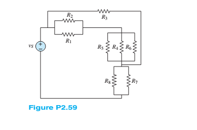
Refer to Figure P2.59. Assume
many nodes are in the circuit? Use KCL and Ohms law to determine:
a. The current in the resistor
b. The equivalent resistance seen by the voltage source
Want to see the full answer?
Check out a sample textbook solution
Chapter 2 Solutions
Principles and Applications of Electrical Engineering


- Two resistors R1 and R2 of 12 Q and 6 N are connected in parallel and this combination is connected in series with a 6.25 Q resistance R3 and a battery which has an internal resistance (in series with the battery e.m.f.) of 0.25 2. Determine the e.m.f. of the battery. (note: the current through 6 ohms is 0.8 A)arrow_forward23. Resistors R1, R2, and R3 have resistances of 15.0 2, 9.0 2, and 8.0 2 Orespectively. R1 and R2 are connected in series, and their combination is in parallel with R3 to form a load across a 6.0-V battery. a. Draw the circuit diagram.arrow_forwardSy A circuit design calls a 1.5 kN resistor to have 4.7 V across its terminals. What would be the expected current? The circuit is built, and the resistance is measured at 1500 2 and the voltage at 4.7 V. What is the current through the resistor? f is iearrow_forward
- The emfs in the figure below are ₁ = 5.00 V and ₂ = 18.0 V. The resistances are R₁ = 17.00, R₂ = 31.00, R3 = 47.002, and R4 = 57.0 Q. Find the magnitude of the current in each resistor when the switch is in the following states. R₂ (a) open I₁ = DI I2 = 13 = I4 = (b) closed I₁ = 12 = R4 13 = I4 = A A A A A A A A S R₁ mw R₂ E₂arrow_forwardHow does the voltage across R1 compare with that through R2? What is the connection between the total current in the circuit and the current through the two resistors? (This is known as Kirchhoff's junction rule.) ... R1 R2 Circuit 4 If you use Circuit 5, do the same rules apply? R1 R2SR3 Circuit 5arrow_forward150 100 + VA- a -4V AVA -7V 81. B b Figure 2 shows a simplified model of a gas-discharge lamp. One characteristic of these lamps is that they exhibit negative resistance; in other words, as current increases the voltage drops further, making such lamps inherently unstable. As such, a current-limiting ballast is required. For the connection shown in the figure: 1. Find the equivalent Thevenin circuit of the lamp. 2. Find the ballast resistance needed to limit the current drawn from a 24-volt source to 6 amperes.arrow_forward
- Good Design Calculate the unloaded voltage Va in the following circuit. Record the calculated value in the table below. Construct the circuit using MultiSim. Energize the circuit and measure V2. Record the measured value in the table below. De-energize the circuit. Assume a 30-ka load resistor is added to the circuit as shown. Calculate the loaded voltage Viz. Record the value in the table below. Construct the circuit using MultiSim. Energize the circuit and measure Via. Record the measured value in the table below. De-energize the circuit. Parameter Calculated (V) Measured (V) Vaarrow_forwardTwo resistors 2.502 and 1.20 are connected in parallel and take a total current of 60A. Find the current flowing through each resistor.arrow_forwardQ2 (a) With the aid of a diagram, briefly describe the Kirchoff Voltage Law. (b) For a circuit in Figure Q2(b), find the value of voltage VR4. 24Ω -W- 482 12V 36Ω 3 6Ω VR4 -W- 12Ω Figure Q2(b) For a circuit indicated in Figure Q2(c), determine the value of voltage Vo, current, I, and resistors RA and RB. (c) I RA RB + 2V, - + Vo + 10 V 2 kQ 4V.arrow_forward
- Three resistors connected in parallel has an equivalent resistance of 3.5 kilo ohms. R, has a resistance of 25 kilo ohms, R, has a voltage drop of 25 V and R3 dissipates power of 25 mW. Find the R2 O a. None of these O b. None of these Oc. 3280 Ohms O d. 3409 Ohmsarrow_forwardIn the circuit shown below, if R1=5 ohm, R2=10 ohm and Vin = 2V. Then the current (I) will equal to: Vino Vout R1 R2 O a. -0.6A O b. 0.4A O c. -0.2A O d. -0.4A Oe. 0.6Aarrow_forwardThe voltage difference between points a and b in the circuit below is provided by a battery that has a voltage Vab = 24 volts. (The battery is not in the picture.) Find the current across R. The individual resistances are R₁ = 2.00, R₂ = 4.00, R3 = 3.0 Q. R4 = 1.0 Q, and R5 = 5.0 0. a O a. 0.70 A O b. 1.3 A OC. 0.40 A O d. 1.6 A O e. 1.0 A ww R₁ R₂ ww 2 www Rs www RA R₁ wwarrow_forward
 Introductory Circuit Analysis (13th Edition)Electrical EngineeringISBN:9780133923605Author:Robert L. BoylestadPublisher:PEARSON
 Delmar's Standard Textbook Of ElectricityElectrical EngineeringISBN:9781337900348Author:Stephen L. HermanPublisher:Cengage Learning
 Programmable Logic ControllersElectrical EngineeringISBN:9780073373843Author:Frank D. PetruzellaPublisher:McGraw-Hill Education
 Fundamentals of Electric CircuitsElectrical EngineeringISBN:9780078028229Author:Charles K Alexander, Matthew SadikuPublisher:McGraw-Hill Education
 Electric Circuits. (11th Edition)Electrical EngineeringISBN:9780134746968Author:James W. Nilsson, Susan RiedelPublisher:PEARSON
 Engineering ElectromagneticsElectrical EngineeringISBN:9780078028151Author:Hayt, William H. (william Hart), Jr, BUCK, John A.Publisher:Mcgraw-hill Education,