
Videos
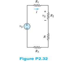
In the circuit of Figure P2.32, assume
Want to see the full answer?
Check out a sample textbook solution
Chapter 2 Solutions
Principles and Applications of Electrical Engineering


- Q11. In the circuit in Figure Q11, find v, i, and the power absorbed by the 4-2 resistor. 20VO v 3102 360 Figure Q11arrow_forwardQ2: in figure shown below find the voltage (v) in this circuit using Kirchhoff's laws. 40 12 V 30 m 80 m 60arrow_forwardFind the Power Dissipated in the load resistance R5 (Power of R5) by using the Mesh Current Method. Student numbers from 180207003 up to 180207037 (including) 1=4A Student numbers from 180207039 up to 190207076 (including) 11=1A V1=10 V V1=4 V V1 R2 R4 out1 out2 R3 4. 11 R1 R5 10 B1 1 V=5*V(out1)arrow_forward
- Finding the direction of the currents. Finding currents given that R2: 10.94 x 10^2 ohmR3: 9.89 x 10^2 ohmR4: 25 ohm Terminal Potential: Battery 1: 5 V using Kirchoff's laws. You will check some of the laws that govern electrical circuitsDirect current: conservation of current in a node, addition of potentialsfor series components, addition of currents for parallel componentsarrow_forwarda. Thévenin's and Norton's theorem are two examples of circuit theorem. With the help of equivalent circuits, distinguish the difference between them.arrow_forwardThe following are the readings taken while conducting an experiment on a wind turbine. what will be the value of open circuit voltage, if the short circuit current is 0.472 A, Maximum power point voltage is 5.32 V, Maximum power point current is 0.111 A and the fill factor is 0.599? Select one: a. 2080 mV b. 2.08 mV c. 8020 V d. 80.2 Varrow_forward
- Find V1 using the circuit of Figure * .down v1 R1 v2 i1 i3 R3 Vs i2 R2 v3 R4 i1 +arrow_forwardIn the circuit shown in the figure, the values of the circuit elements are given below.Accordingly, what is the voltage across the resistor R3 at t=0.4 seconds?R1 = 10 ohmsR2 = 8 ohmsR3 = 5 ohmsL = 8 hensC = 1/2 faradV = 14 u(t) VI = 8/5 u(t) Aarrow_forward2. a) Use Kirchhoff's current law to solve for the currents 11, 12, I3, I4, Is and I6 For the circuit-2.a). b) Find the equivalent resistance across terminal P and Q in Circuit-2b) if (i) Switch SI is ON, S2 is ON, S3 OFF and S4 OFF (ii) Switch S1 is ON, S2 is OFF, S3 ON and S4 ON (Values of all the Resistors are in Ohms).arrow_forward
- Use superposition to compute for the DC voltage levels for node B, C, and D. The dependent current source is equal to I1=hfeIb, hfe=177. What is the DC current Ib?arrow_forwardConsider the circuit shown in below Figure, Find values of the resistances R1 and R2 that cause the voltages v1 and v2 to be v1 = 1 V and v2 = 2 V. 500 2 + + R1 R2 () 5 mA 3 mA V1 V2 6:03 PM 50°F Clear 2/18/2022 P Type here to search Del End F10 PgUp. F11 PgDn F12 PrtScn Home F7 F2 F3 F1 & ) Backspace %23 %24 % 4. 5 7 8. 9. 2 3 W.arrow_forwardConsider the circuit in figure 1. a: Find Thevenin equivalent circuit with the respect to terminals a-b. b: Find the load resistance, Ri, that enables the circuit to deliver maximum power transfer to the terminals a-b. c: Find the maximum power delivered to Ri. IS A 1852 1012 www figme... a €1222 Ri o barrow_forward
 Introductory Circuit Analysis (13th Edition)Electrical EngineeringISBN:9780133923605Author:Robert L. BoylestadPublisher:PEARSON
 Delmar's Standard Textbook Of ElectricityElectrical EngineeringISBN:9781337900348Author:Stephen L. HermanPublisher:Cengage Learning
 Programmable Logic ControllersElectrical EngineeringISBN:9780073373843Author:Frank D. PetruzellaPublisher:McGraw-Hill Education
 Fundamentals of Electric CircuitsElectrical EngineeringISBN:9780078028229Author:Charles K Alexander, Matthew SadikuPublisher:McGraw-Hill Education
 Electric Circuits. (11th Edition)Electrical EngineeringISBN:9780134746968Author:James W. Nilsson, Susan RiedelPublisher:PEARSON
 Engineering ElectromagneticsElectrical EngineeringISBN:9780078028151Author:Hayt, William H. (william Hart), Jr, BUCK, John A.Publisher:Mcgraw-hill Education,