
Principles and Applications of Electrical Engineering
6th Edition
ISBN: 9780073529592
Author: Giorgio Rizzoni Professor of Mechanical Engineering, James A. Kearns Dr.
Publisher: McGraw-Hill Education
expand_more
expand_more
format_list_bulleted
Concept explainers
Videos
Textbook Question
Chapter 2, Problem 2.72HP
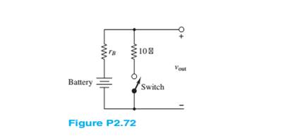
The circuit of Figure P2.72 is used to measure the internal impedance of a battery. The battery being tested is a NiMH battery cell.
a. A fresh battery is being tested, and it is found that the voltage
b. The same battery is tested one year later.
Expert Solution & Answer
Want to see the full answer?
Check out a sample textbook solution
Students have asked these similar questions
liting
Q9.
For the circuit shown in Figure C9, Calculate the following
i)
Current through the Silicon diode (Isi).
ii)
Current through the Resistor R2 (1).
iii) Current through the diode D4 (IGe4).
iv) Voltage at points V3 and V4.
Is
D1.
D2
Si
Si
oV4
RI
1.3K2
R3
2.7K
R2
3K2
IGe4|
15V
D5
Si
03
D4
Ge
Ge
V2
1V
Figure C9
a. If you do not go completely around the loop when applying Kirchhoff’s voltage law, then
the algebraic sum of the voltages cannot be determined
the algebraic sum of the voltages will always be positive
the algebraic sum of the voltages will always be negative
the algebraic sum is the voltage between the start and finish points
b. A p -type semiconductor is a semiconductor doped with
impurity atoms whose electron valence is +4
pentavalent impurity atoms
trivalent impurity atoms
Diodes Are Connected In
Series To Share A Total...
21
Question
• Two diodes are connected in series to share
a total reverse voltage of VD=D 5 KV. Reverse leakage
currents of the diodes are ID1=30 mA and Ip2=35 mA.
- Find Vp1 and Vp2 for R,=R2=100 k2
- Find R, and R2 for VD1=VD2
R1
VD1
Hint:
Is=L,+IRj= I,2+IR2
VD
R2
VD2
Chapter 2 Solutions
Principles and Applications of Electrical Engineering
Ch. 2 - A free electron has an initial potential energy...Ch. 2 - The units for voltage, current, and resistance are...Ch. 2 - A particular fully charged battery can deliver...Ch. 2 - The charge cycle shown in Figure P2.4 is an...Ch. 2 - Batteries (e.g., lead-acid batteries) store...Ch. 2 - What determines: a. The current through an ideal...Ch. 2 - An automotive battery is rated at 120 A-h. This...Ch. 2 - A car battery kept in storage in the basement...Ch. 2 - Suppose the current through a wire is given by the...Ch. 2 - The charge cycle shown in Figure P2.10 is...
Ch. 2 - The charging scheme used in Figure P2.11 is...Ch. 2 - The charging scheme used in Figure P2.12 is...Ch. 2 - Use KCL to determine the unknown currents in the...Ch. 2 - Use KCL to find the current i1 and i2 in Figure...Ch. 2 - Use KCL to find the current i1,i2, and i3 in the...Ch. 2 - Use KVL to find the voltages v1,v2, and v3 in...Ch. 2 - Use KCL to determine the current i1,i2,i3, and i4...Ch. 2 - In the circuits of Figure P2.18, the directions...Ch. 2 - Find the power delivered by each source in Figure...Ch. 2 - Determine whether each element in Figure P2.20 is...Ch. 2 - In the circuit of Figure P2.21, determine the...Ch. 2 - For the circuit shown in Figure P2.22: a....Ch. 2 - For the circuit shown in Figure P2.23,...Ch. 2 - For the circuit shown in Figure P2.24, determine...Ch. 2 - For the circuit shown in Figure P2.25, determine...Ch. 2 - Prob. 2.26HPCh. 2 - Prob. 2.27HPCh. 2 - Prob. 2.28HPCh. 2 - Prob. 2.29HPCh. 2 - Prob. 2.30HPCh. 2 - Prob. 2.31HPCh. 2 - In the circuit of Figure P2.32, assume v2=vs/6 and...Ch. 2 - Prob. 2.33HPCh. 2 - An incandescent light bulb rated at 100 W will...Ch. 2 - An incandescent lightbulb rated at 60 W...Ch. 2 - Refer to Figure P2.36, and assume that...Ch. 2 - Refer to Figure P2.37, and assume that...Ch. 2 - Refer to Figure P2.38, and assume...Ch. 2 - Prob. 2.39HPCh. 2 - With no load attached, the voltage at the...Ch. 2 - Prob. 2.41HPCh. 2 - For the circuits of Figure P2.42, determine the...Ch. 2 - At an engineering site, a 1-hp motor is placed...Ch. 2 - Cheap resistors are fabricated by depositing a...Ch. 2 - Prob. 2.45HPCh. 2 - Use KCL and Ohm’s law to determine the current...Ch. 2 - Refer to Figure P2.13. Assume R0=1,R1=2,R2=3,R3=4...Ch. 2 - Apply KCL and Ohm’s law to find the power supplied...Ch. 2 - Refer to Figure P2.49 and assume...Ch. 2 - Refer to Figure P2.49 and assume...Ch. 2 - Prob. 2.51HPCh. 2 - The voltage divider network of Figure P2.52 is...Ch. 2 - Find the equivalent resistance seen by the source...Ch. 2 - Find the equivalent resistance seen by the source...Ch. 2 - In the circuit of Figure P2.55, the power absorbed...Ch. 2 - Find the equivalent resistance between terminals...Ch. 2 - For the circuit shown in Figure P2.57, find the...Ch. 2 - For the circuit shown in Figure P2.58,find the...Ch. 2 - Refer to Figure P2.59. Assume...Ch. 2 - Find the equivalent resistance seen by the source...Ch. 2 - For the circuit shown in Figure P2.61. assume...Ch. 2 - Determine the equivalent resistance of the...Ch. 2 - For the circuit shown in Figure P2.58, assume...Ch. 2 - In the circuit of Figure P2.64, find the...Ch. 2 - Refer to Figure P2.64 and determine the equivalent...Ch. 2 - Find the equivalent resistance seen by the source...Ch. 2 - Determine the voltage vo between nodes A and Bin...Ch. 2 - Refer to Figure P2.68 and assume...Ch. 2 - Prob. 2.69HPCh. 2 - Prob. 2.70HPCh. 2 - Prob. 2.71HPCh. 2 - The circuit of Figure P2.72 is used to measure the...Ch. 2 - Consider the practical ammeter, depicted in Figure...Ch. 2 - Prob. 2.74HPCh. 2 - Prob. 2.75HPCh. 2 - Prob. 2.76HPCh. 2 - A voltmeter is used to determine the voltage...Ch. 2 - Prob. 2.78HPCh. 2 - Figure P2.79 shows an aluminum cantilevered beam...Ch. 2 - Refer to Figure P2.79 but assume that the...
Knowledge Booster


Learn more about
Need a deep-dive on the concept behind this application? Look no further. Learn more about this topic, electrical-engineering and related others by exploring similar questions and additional content below.Similar questions
- 1. The no-load terminal voltage of a battery is 30 V. The terminal voltage drops to 22 V when supplying a current of 5 A. Determine the emf and the internal resistance of this battery. Ans. r= 1.6 ohm 2. Two identical zinc carbon batteries are available. When connected in series, they supply 0.5 A to a 4 ohm resistor. When connected in parallel, they supply 0.4 A to a 5 ohm resistor. Determine the emf and internal resistance of each battery. Ans. 2.667 V and 3.333 ohm 3. When supplying a current of 5 A, the terminal voltage of a battery is 15 V. The battery is then recharged at a rate of 3 A and the terminal voltage is found to be 21 V. Determine the emf and the Internal resistance of the battery. Ans. 18.75 V and 0.75 ohm 4. A battery with an emf of 12 V and an internal resistance of 0.8 ohm is to be recharged through a 20 V source. (a) show by means of a diagram the connection of the circuit elements. (b) What is the current in the circuit? (c) The recharging current is to be…arrow_forwardShown below is a diode circuit. If the input signal Vs = 42 Vp-p and the DC voltage Vdc = 8 V, what is the output voltage (in volts) of the circuit during the positive alteration? No need to show your solution. Just write your numeric answer on the space provided. Round off your answer to 2 decimal places. C1 Si D1 Vo Vs 1.0kn Vdcarrow_forwardQuestion 2 Find I₁, I2, Va, and V₁ in the following circuit. Use diode constant voltage drop (CVD) model with VD = 0.5 V. You must show your work in details and you must verify your assumptions. The circuit parameters are:, V₁ = 20, V₂ = -10, Is = 2, and R₁ D₁ H1₁ V₁ V Va I, mA D₂ -oVb R₁ kN V₂ V 100KDarrow_forward
- Subject: Electronics Engineering To study V-I characteristics of the semiconductor diode and determine D.C & A.C resistance. Write in your own language what you learn from this experimentarrow_forward60 V D1 D2 2 kohm D4 D3 -60 V Assume that an input signal is applied to the circuit given above, as shown in the figure next to it. Accordingly, answer the following questions. The diodes used are silicon diodes, their operating voltages are 0.7 volts, and can be omitted because their resistance is very small. Write the name of this circuit, thinking about which circuit we do in the courses is equivalent to the purpose.arrow_forwardAn ideal battery of terminal voltage 22 volts charges two practical batteries connected in parallel to each other. The parallel connection of the said practical batteries is connected across the ideal battery. The two practical batteries have the following specifications: 10 volts, 0.2 ohm; 8 volts, 0.5 ohm. Determine the total current being delivered by the source.arrow_forward
- Note: Some figures show MOSFET or Diode- treat them as ideal switches S1, S2. 1) In the circuit below, what is the output voltage, if the input voltage is 100 V and the left switch (Sw1 is on 75% of a period of 100 us? Use the energy balance principle taught in class. Vin Sw1 D1 L1 C1 Voutarrow_forwardIn the figure shown, you measure a potential of +3V at the junction of R1 and R2. Remember, potentials are always with respect to the ground. Next, you measure 0 V at the junction of the diode and the 5k2 resistor. Name some possible troubles. +12 V R, 30 k2 R3 5 k2 R2 10 k2arrow_forwardQ2: Draw the output waveform for the three shown circuits. 1- R +10V D D V. 0- 5V 5 V -10 V Diodes are IN914. 2- Assume Vm=20V, show the Vdc on the graph D2 Ds 3- Assume Vm=18V and V-5V. 34arrow_forward
- In the following figure V, = 0 V and V2 = 8 V , which diode will conduct( assume ideal diodes) D, IkO ww V • D; IkQ 10k2 V, - ww E. D,only F. Dzonly G. D, and D2 H. neither D, nor D2 Dzonly neither D, nor D2 D1 and D2 D1onlyarrow_forwarduse the constant voltage drop model in analyzing the diode circuit below: 10 92 V₁ (+ M 1 V D₁ If V₁ is -3 V, what would be the state of the diodes? A. D₁ and D₂ are both OFF C B. D₁ is OFF and D₂ is ON - 1 V D₂ C. D₁ is ON and D₂ is OFF D. D₁ and D₂ are both ON + 1092 Voarrow_forwardQ2: Draw the output waveform for the three shown circuits. 1- +10 V 1Okf D D2 -0 "A -10 V 5V 5 V Diodes are IN914. 2- Assume Vm=20V, show the Vdc on the graph D D2 R Da 3- Assume Vm=18V and V-5V. Rarrow_forward
arrow_back_ios
SEE MORE QUESTIONS
arrow_forward_ios
Recommended textbooks for you
 Introductory Circuit Analysis (13th Edition)Electrical EngineeringISBN:9780133923605Author:Robert L. BoylestadPublisher:PEARSON
 Delmar's Standard Textbook Of ElectricityElectrical EngineeringISBN:9781337900348Author:Stephen L. HermanPublisher:Cengage Learning
 Programmable Logic ControllersElectrical EngineeringISBN:9780073373843Author:Frank D. PetruzellaPublisher:McGraw-Hill Education
 Fundamentals of Electric CircuitsElectrical EngineeringISBN:9780078028229Author:Charles K Alexander, Matthew SadikuPublisher:McGraw-Hill Education
 Electric Circuits. (11th Edition)Electrical EngineeringISBN:9780134746968Author:James W. Nilsson, Susan RiedelPublisher:PEARSON
 Engineering ElectromagneticsElectrical EngineeringISBN:9780078028151Author:Hayt, William H. (william Hart), Jr, BUCK, John A.Publisher:Mcgraw-hill Education,
Introductory Circuit Analysis (13th Edition)
Electrical Engineering
ISBN:9780133923605
Author:Robert L. Boylestad
Publisher:PEARSON
Delmar's Standard Textbook Of Electricity
Electrical Engineering
ISBN:9781337900348
Author:Stephen L. Herman
Publisher:Cengage Learning
Programmable Logic Controllers
Electrical Engineering
ISBN:9780073373843
Author:Frank D. Petruzella
Publisher:McGraw-Hill Education
Fundamentals of Electric Circuits
Electrical Engineering
ISBN:9780078028229
Author:Charles K Alexander, Matthew Sadiku
Publisher:McGraw-Hill Education
Electric Circuits. (11th Edition)
Electrical Engineering
ISBN:9780134746968
Author:James W. Nilsson, Susan Riedel
Publisher:PEARSON
Engineering Electromagnetics
Electrical Engineering
ISBN:9780078028151
Author:Hayt, William H. (william Hart), Jr, BUCK, John A.
Publisher:Mcgraw-hill Education,
Star Delta Starter Explained - Working Principle; Author: The Engineering Mindset;https://www.youtube.com/watch?v=h89TTwlNnpY;License: Standard Youtube License