
Concept explainers
Videos
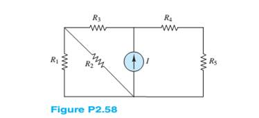
For the circuit shown in Figure P2.58,find the equivalent resistance seen by the current source. How many nodes are in the circuit? Assume
Want to see the full answer?
Check out a sample textbook solution
Chapter 2 Solutions
Principles and Applications of Electrical Engineering


- Sy A circuit design calls a 1.5 kN resistor to have 4.7 V across its terminals. What would be the expected current? The circuit is built, and the resistance is measured at 1500 2 and the voltage at 4.7 V. What is the current through the resistor? f is iearrow_forwardQ1: Use a qualitative analysis to identify the filter type for the circuit shown in Figure-1 below. Hence use a quantitative analysis to calculate its parameters. Vin L Vout Figure 1arrow_forwardThe element shown in figure a) is known as Spinner and has the following relations v - i: v1 = R0i2, v2 = —R0i1. Find an equivalent circuit from the terminals v1, i1 of figure b) that contains only two basic elements connected in parallel, figure c).arrow_forward
- Three resistors of 50 N, 100 N and an unknown resistance R are connected in parallel and the combination is connected to a 25 V source. If the total current delivered by the source is 1 A, determine the following: A. The value of R (Ans. R = 100 2) B. The current in each resistor (Ans. I1 = 0.5 A, I2 = I3 = 0.25 A) C. Which resistor dissipates the highest power? Show your solution. (Ans. R1)arrow_forwardSince R1=9282.13ohm, R2=3403.87ohm and Ri=Infinite in the circuit given in the figure, write the equivalent resistance in Ohms between the terminals A-B.arrow_forward1. Using Series-Parallel concept, Find the following for the given circuit. The value of the power supply and resistances are given in Page-4. a) the current supplied by the source b) the voltage drops across each resistor c) the r dissipated by R3 R1=45kn R2=2kn R3=22kQ R4=14kn R5=17kn R6=85kn V1=24 v R₁ R₂ V₁ R₂ R₂ R₂arrow_forward
- Determine the mathematical model equations for the electrical circuit shown in figure 2. The circuit is consisting of two resistors, two inductors and a capacitor. A voltage Va is applied to the circuit. Derive an expression for the mathematical model of the following circuit. R1 L2 i1 13 14 16 + O- i2 i5 R2 L1 Va C Figure (2) the electrical circuit uarrow_forwardFinding the direction of the currents. Finding currents given that R2: 10.94 x 10^2 ohmR3: 9.89 x 10^2 ohmR4: 25 ohm Terminal Potential: Battery 1: 5 V using Kirchoff's laws. You will check some of the laws that govern electrical circuitsDirect current: conservation of current in a node, addition of potentialsfor series components, addition of currents for parallel componentsarrow_forwardCreate a combination circuit that has R1= 10 ohms, R2 = 20 ohms, and R3 = 30 ohms. R1 will be in series connected to R2 and R3 in parallel. If 10v total were applied… solve the circuit and show all the values including power for each component.arrow_forward
- What is the current read by the ammeter in the circuit below? Let R1 = 1 kiloohm, R2 = 2 kiloohm, R3 = 3 kiloohm, and the emf of the ideal source is 5 volts. Input R1, R2, and R3 for resistors Ri, R2, and R3 respectively. Input E for the emf E. Use context clues to figure out if you need to input a numerical value, variable, word, etc. All numerical answers should be in three significant figures. R1 R2 R3 + First we calculate the current across each resistor. From Ohm's law, we arrive at a general formula for current: | =arrow_forwardA variable resistive load has a 10-10092 range, and is connected across the load terminals of a circuit. This circuit has a Thevenin voltage and resistance of 150 V and 25 2, respectively. What should be the resistance of the variable resistive load so that it will consume 80% of the max power that this circuit can deliver? (Round-off to two decimal places)arrow_forwardThe figure below shows the resistors wired in a different way-a combination of series and parallel. We can consider R₁, to be the resistance of wires leading to R₂ and R³ a. Find the total resistance. b. What is the IR drop in R₁? c. Find the current I through R₂. d. What power is dissipated by R₂?arrow_forward
 Introductory Circuit Analysis (13th Edition)Electrical EngineeringISBN:9780133923605Author:Robert L. BoylestadPublisher:PEARSON
 Delmar's Standard Textbook Of ElectricityElectrical EngineeringISBN:9781337900348Author:Stephen L. HermanPublisher:Cengage Learning
 Programmable Logic ControllersElectrical EngineeringISBN:9780073373843Author:Frank D. PetruzellaPublisher:McGraw-Hill Education
 Fundamentals of Electric CircuitsElectrical EngineeringISBN:9780078028229Author:Charles K Alexander, Matthew SadikuPublisher:McGraw-Hill Education
 Electric Circuits. (11th Edition)Electrical EngineeringISBN:9780134746968Author:James W. Nilsson, Susan RiedelPublisher:PEARSON
 Engineering ElectromagneticsElectrical EngineeringISBN:9780078028151Author:Hayt, William H. (william Hart), Jr, BUCK, John A.Publisher:Mcgraw-hill Education,