
Principles and Applications of Electrical Engineering
6th Edition
ISBN: 9780073529592
Author: Giorgio Rizzoni Professor of Mechanical Engineering, James A. Kearns Dr.
Publisher: McGraw-Hill Education
expand_more
expand_more
format_list_bulleted
Concept explainers
Videos
Textbook Question
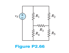
Chapter 2, Problem 2.66HP
Find the equivalent resistance seen by the source in Figure P2.66. How many nodes are in the circuit?Assume:
Expert Solution & Answer
Want to see the full answer?
Check out a sample textbook solution
Students have asked these similar questions
How does the voltage across R1 compare with that through R2? What is the connection between the total current in the circuit and
the current through the two resistors? (This is known as Kirchhoff's junction rule.)
...
R1
R2
Circuit 4
If you use Circuit 5, do the same rules apply?
R1 R2SR3
Circuit 5
Sy A circuit design calls a 1.5 kN resistor to have 4.7 V across its terminals. What would be the expected
current? The circuit is built, and the resistance is measured at 1500 2 and the voltage at 4.7 V. What is the
current through the resistor?
f is ie
Two batteries are connected in parallel delivering power to a power resistor. The first battery has an open circuit voltage of 12.6 V and an internal resistance of 0.2 ohm. The second battery has an open circuit voltage of 12.2 V and an internal resistance of 0.3 ohm. Find the maximum power delivered to the load resistance.
Chapter 2 Solutions
Principles and Applications of Electrical Engineering
Ch. 2 - A free electron has an initial potential energy...Ch. 2 - The units for voltage, current, and resistance are...Ch. 2 - A particular fully charged battery can deliver...Ch. 2 - The charge cycle shown in Figure P2.4 is an...Ch. 2 - Batteries (e.g., lead-acid batteries) store...Ch. 2 - What determines: a. The current through an ideal...Ch. 2 - An automotive battery is rated at 120 A-h. This...Ch. 2 - A car battery kept in storage in the basement...Ch. 2 - Suppose the current through a wire is given by the...Ch. 2 - The charge cycle shown in Figure P2.10 is...
Ch. 2 - The charging scheme used in Figure P2.11 is...Ch. 2 - The charging scheme used in Figure P2.12 is...Ch. 2 - Use KCL to determine the unknown currents in the...Ch. 2 - Use KCL to find the current i1 and i2 in Figure...Ch. 2 - Use KCL to find the current i1,i2, and i3 in the...Ch. 2 - Use KVL to find the voltages v1,v2, and v3 in...Ch. 2 - Use KCL to determine the current i1,i2,i3, and i4...Ch. 2 - In the circuits of Figure P2.18, the directions...Ch. 2 - Find the power delivered by each source in Figure...Ch. 2 - Determine whether each element in Figure P2.20 is...Ch. 2 - In the circuit of Figure P2.21, determine the...Ch. 2 - For the circuit shown in Figure P2.22: a....Ch. 2 - For the circuit shown in Figure P2.23,...Ch. 2 - For the circuit shown in Figure P2.24, determine...Ch. 2 - For the circuit shown in Figure P2.25, determine...Ch. 2 - Prob. 2.26HPCh. 2 - Prob. 2.27HPCh. 2 - Prob. 2.28HPCh. 2 - Prob. 2.29HPCh. 2 - Prob. 2.30HPCh. 2 - Prob. 2.31HPCh. 2 - In the circuit of Figure P2.32, assume v2=vs/6 and...Ch. 2 - Prob. 2.33HPCh. 2 - An incandescent light bulb rated at 100 W will...Ch. 2 - An incandescent lightbulb rated at 60 W...Ch. 2 - Refer to Figure P2.36, and assume that...Ch. 2 - Refer to Figure P2.37, and assume that...Ch. 2 - Refer to Figure P2.38, and assume...Ch. 2 - Prob. 2.39HPCh. 2 - With no load attached, the voltage at the...Ch. 2 - Prob. 2.41HPCh. 2 - For the circuits of Figure P2.42, determine the...Ch. 2 - At an engineering site, a 1-hp motor is placed...Ch. 2 - Cheap resistors are fabricated by depositing a...Ch. 2 - Prob. 2.45HPCh. 2 - Use KCL and Ohm’s law to determine the current...Ch. 2 - Refer to Figure P2.13. Assume R0=1,R1=2,R2=3,R3=4...Ch. 2 - Apply KCL and Ohm’s law to find the power supplied...Ch. 2 - Refer to Figure P2.49 and assume...Ch. 2 - Refer to Figure P2.49 and assume...Ch. 2 - Prob. 2.51HPCh. 2 - The voltage divider network of Figure P2.52 is...Ch. 2 - Find the equivalent resistance seen by the source...Ch. 2 - Find the equivalent resistance seen by the source...Ch. 2 - In the circuit of Figure P2.55, the power absorbed...Ch. 2 - Find the equivalent resistance between terminals...Ch. 2 - For the circuit shown in Figure P2.57, find the...Ch. 2 - For the circuit shown in Figure P2.58,find the...Ch. 2 - Refer to Figure P2.59. Assume...Ch. 2 - Find the equivalent resistance seen by the source...Ch. 2 - For the circuit shown in Figure P2.61. assume...Ch. 2 - Determine the equivalent resistance of the...Ch. 2 - For the circuit shown in Figure P2.58, assume...Ch. 2 - In the circuit of Figure P2.64, find the...Ch. 2 - Refer to Figure P2.64 and determine the equivalent...Ch. 2 - Find the equivalent resistance seen by the source...Ch. 2 - Determine the voltage vo between nodes A and Bin...Ch. 2 - Refer to Figure P2.68 and assume...Ch. 2 - Prob. 2.69HPCh. 2 - Prob. 2.70HPCh. 2 - Prob. 2.71HPCh. 2 - The circuit of Figure P2.72 is used to measure the...Ch. 2 - Consider the practical ammeter, depicted in Figure...Ch. 2 - Prob. 2.74HPCh. 2 - Prob. 2.75HPCh. 2 - Prob. 2.76HPCh. 2 - A voltmeter is used to determine the voltage...Ch. 2 - Prob. 2.78HPCh. 2 - Figure P2.79 shows an aluminum cantilevered beam...Ch. 2 - Refer to Figure P2.79 but assume that the...
Knowledge Booster


Learn more about
Need a deep-dive on the concept behind this application? Look no further. Learn more about this topic, electrical-engineering and related others by exploring similar questions and additional content below.Similar questions
- Three resistors of 50 N, 100 N and an unknown resistance R are connected in parallel and the combination is connected to a 25 V source. If the total current delivered by the source is 1 A, determine the following: A. The value of R (Ans. R = 100 2) B. The current in each resistor (Ans. I1 = 0.5 A, I2 = I3 = 0.25 A) C. Which resistor dissipates the highest power? Show your solution. (Ans. R1)arrow_forwardThe figure below shows resistors wired in a combination of series and parallel. (a) Find the equivalent resistance of the circuit. (b) What is the potential drop V1 across resistor R1? (c) Find the current I2 through resistor R2. (d) What power is dissipated by R2?arrow_forwardA variable resistive load has a 10-10092 range, and is connected across the load terminals of a circuit. This circuit has a Thevenin voltage and resistance of 150 V and 25 N, respectively. What should be the resistance of the variable resistive load so that it will consume 80% of the max power that this circuit can deliver? (Round-off to two decimal places)arrow_forward
- A variable resistive load has a 10-10092 range, and is connected across the load terminals of a circuit. This circuit has a Thevenin voltage and resistance of 150 V and 25 2, respectively. What should be the resistance of the variable resistive load so that it will consume 80% of the max power that this circuit can deliver? (Round-off to two decimal places)arrow_forwardThe element shown in figure a) is known as Spinner and has the following relations v - i: v1 = R0i2, v2 = —R0i1. Find an equivalent circuit from the terminals v1, i1 of figure b) that contains only two basic elements connected in parallel, figure c).arrow_forwardQ1: Use a qualitative analysis to identify the filter type for the circuit shown in Figure-1 below. Hence use a quantitative analysis to calculate its parameters. Vin L Vout Figure 1arrow_forward
- Q1) For the circuits shown in figure below, obtain the equivalent resistance at terminals a-b. 200 wwarrow_forwardb) The circuit in Figure Q2(b) is referred. i. Show the supernode in the circuit. Explain the reason for your answer. ii. By using nodal analysis with supernode, solve for the node voltages at each assigned nodes in the circuit. 2 A 12 V Figure Q2(b)arrow_forward1. Using Series-Parallel concept, Find the following for the given circuit. The value of the power supply and resistances are given in Page-4. a) the current supplied by the source b) the voltage drops across each resistor c) the r dissipated by R3 R1=45kn R2=2kn R3=22kQ R4=14kn R5=17kn R6=85kn V1=24 v R₁ R₂ V₁ R₂ R₂ R₂arrow_forward
- For R1=55, R2=D125, R33D135, R4=15, R5=40, R63D90 and V1=4 V in the shown figure, use circuit reduction and current/voltage division rules to calculate the following: R6 R1 R5 R3 R2 V1 V2 R4 V13= V2=arrow_forwardI want the solution Q2/ Q3/ Q4/arrow_forwardThe circuit below(left) displays a schematic diagram of a battery. The voltage measured by U1 is called the terminal voltage given R1 = 1 ohm. In the circuit below(right), the terminal voltage of each of the battery-resistor combination is VT = 1.5 volts. Find the current passing through R1, R2, R5arrow_forward
arrow_back_ios
SEE MORE QUESTIONS
arrow_forward_ios
Recommended textbooks for you
 Introductory Circuit Analysis (13th Edition)Electrical EngineeringISBN:9780133923605Author:Robert L. BoylestadPublisher:PEARSON
 Delmar's Standard Textbook Of ElectricityElectrical EngineeringISBN:9781337900348Author:Stephen L. HermanPublisher:Cengage Learning
 Programmable Logic ControllersElectrical EngineeringISBN:9780073373843Author:Frank D. PetruzellaPublisher:McGraw-Hill Education
 Fundamentals of Electric CircuitsElectrical EngineeringISBN:9780078028229Author:Charles K Alexander, Matthew SadikuPublisher:McGraw-Hill Education
 Electric Circuits. (11th Edition)Electrical EngineeringISBN:9780134746968Author:James W. Nilsson, Susan RiedelPublisher:PEARSON
 Engineering ElectromagneticsElectrical EngineeringISBN:9780078028151Author:Hayt, William H. (william Hart), Jr, BUCK, John A.Publisher:Mcgraw-hill Education,
Introductory Circuit Analysis (13th Edition)
Electrical Engineering
ISBN:9780133923605
Author:Robert L. Boylestad
Publisher:PEARSON
Delmar's Standard Textbook Of Electricity
Electrical Engineering
ISBN:9781337900348
Author:Stephen L. Herman
Publisher:Cengage Learning
Programmable Logic Controllers
Electrical Engineering
ISBN:9780073373843
Author:Frank D. Petruzella
Publisher:McGraw-Hill Education
Fundamentals of Electric Circuits
Electrical Engineering
ISBN:9780078028229
Author:Charles K Alexander, Matthew Sadiku
Publisher:McGraw-Hill Education
Electric Circuits. (11th Edition)
Electrical Engineering
ISBN:9780134746968
Author:James W. Nilsson, Susan Riedel
Publisher:PEARSON
Engineering Electromagnetics
Electrical Engineering
ISBN:9780078028151
Author:Hayt, William H. (william Hart), Jr, BUCK, John A.
Publisher:Mcgraw-hill Education,
Star Delta Starter Explained - Working Principle; Author: The Engineering Mindset;https://www.youtube.com/watch?v=h89TTwlNnpY;License: Standard Youtube License