
Principles and Applications of Electrical Engineering
6th Edition
ISBN: 9780073529592
Author: Giorgio Rizzoni Professor of Mechanical Engineering, James A. Kearns Dr.
Publisher: McGraw-Hill Education
expand_more
expand_more
format_list_bulleted
Concept explainers
Videos
Textbook Question
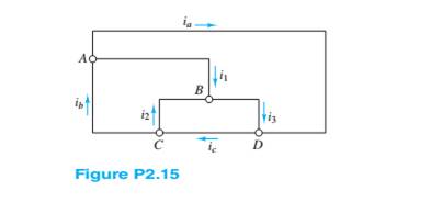
Chapter 2, Problem 2.15HP
Use KCL to find the current
Expert Solution & Answer
Want to see the full answer?
Check out a sample textbook solution
Students have asked these similar questions
In the figure the current in resistance 6 is i = 1.43 A and the resistances are R₁ = R₂ = R3
= 1.68 2, R₂ = 15.1 Q2, R5 = 7.41 Q2, and R6 = 4.57 2. What is the emf of the ideal battery?
E
www
R₁
O a. 25.7V
O b. 52.3 V
O C. 47.2 V
O d.
21.4 V
O e. 6.54 V
R3
www
R₂
www
R₁
R₂
16
R6
Figure 2.1 shows a simple circuit. Explain why using a DMM tomeasure the DC voltage across resistor R2 might lead to inaccurate results. Include in your answer how the value of R2 might affect the size of the error and provide some circuit diagrams and equations to showhow to calculate the error.
Redraw the circuit diagram of the simplified figure and find the current I flowing at resistance 8 ohm.
Chapter 2 Solutions
Principles and Applications of Electrical Engineering
Ch. 2 - A free electron has an initial potential energy...Ch. 2 - The units for voltage, current, and resistance are...Ch. 2 - A particular fully charged battery can deliver...Ch. 2 - The charge cycle shown in Figure P2.4 is an...Ch. 2 - Batteries (e.g., lead-acid batteries) store...Ch. 2 - What determines: a. The current through an ideal...Ch. 2 - An automotive battery is rated at 120 A-h. This...Ch. 2 - A car battery kept in storage in the basement...Ch. 2 - Suppose the current through a wire is given by the...Ch. 2 - The charge cycle shown in Figure P2.10 is...
Ch. 2 - The charging scheme used in Figure P2.11 is...Ch. 2 - The charging scheme used in Figure P2.12 is...Ch. 2 - Use KCL to determine the unknown currents in the...Ch. 2 - Use KCL to find the current i1 and i2 in Figure...Ch. 2 - Use KCL to find the current i1,i2, and i3 in the...Ch. 2 - Use KVL to find the voltages v1,v2, and v3 in...Ch. 2 - Use KCL to determine the current i1,i2,i3, and i4...Ch. 2 - In the circuits of Figure P2.18, the directions...Ch. 2 - Find the power delivered by each source in Figure...Ch. 2 - Determine whether each element in Figure P2.20 is...Ch. 2 - In the circuit of Figure P2.21, determine the...Ch. 2 - For the circuit shown in Figure P2.22: a....Ch. 2 - For the circuit shown in Figure P2.23,...Ch. 2 - For the circuit shown in Figure P2.24, determine...Ch. 2 - For the circuit shown in Figure P2.25, determine...Ch. 2 - Prob. 2.26HPCh. 2 - Prob. 2.27HPCh. 2 - Prob. 2.28HPCh. 2 - Prob. 2.29HPCh. 2 - Prob. 2.30HPCh. 2 - Prob. 2.31HPCh. 2 - In the circuit of Figure P2.32, assume v2=vs/6 and...Ch. 2 - Prob. 2.33HPCh. 2 - An incandescent light bulb rated at 100 W will...Ch. 2 - An incandescent lightbulb rated at 60 W...Ch. 2 - Refer to Figure P2.36, and assume that...Ch. 2 - Refer to Figure P2.37, and assume that...Ch. 2 - Refer to Figure P2.38, and assume...Ch. 2 - Prob. 2.39HPCh. 2 - With no load attached, the voltage at the...Ch. 2 - Prob. 2.41HPCh. 2 - For the circuits of Figure P2.42, determine the...Ch. 2 - At an engineering site, a 1-hp motor is placed...Ch. 2 - Cheap resistors are fabricated by depositing a...Ch. 2 - Prob. 2.45HPCh. 2 - Use KCL and Ohm’s law to determine the current...Ch. 2 - Refer to Figure P2.13. Assume R0=1,R1=2,R2=3,R3=4...Ch. 2 - Apply KCL and Ohm’s law to find the power supplied...Ch. 2 - Refer to Figure P2.49 and assume...Ch. 2 - Refer to Figure P2.49 and assume...Ch. 2 - Prob. 2.51HPCh. 2 - The voltage divider network of Figure P2.52 is...Ch. 2 - Find the equivalent resistance seen by the source...Ch. 2 - Find the equivalent resistance seen by the source...Ch. 2 - In the circuit of Figure P2.55, the power absorbed...Ch. 2 - Find the equivalent resistance between terminals...Ch. 2 - For the circuit shown in Figure P2.57, find the...Ch. 2 - For the circuit shown in Figure P2.58,find the...Ch. 2 - Refer to Figure P2.59. Assume...Ch. 2 - Find the equivalent resistance seen by the source...Ch. 2 - For the circuit shown in Figure P2.61. assume...Ch. 2 - Determine the equivalent resistance of the...Ch. 2 - For the circuit shown in Figure P2.58, assume...Ch. 2 - In the circuit of Figure P2.64, find the...Ch. 2 - Refer to Figure P2.64 and determine the equivalent...Ch. 2 - Find the equivalent resistance seen by the source...Ch. 2 - Determine the voltage vo between nodes A and Bin...Ch. 2 - Refer to Figure P2.68 and assume...Ch. 2 - Prob. 2.69HPCh. 2 - Prob. 2.70HPCh. 2 - Prob. 2.71HPCh. 2 - The circuit of Figure P2.72 is used to measure the...Ch. 2 - Consider the practical ammeter, depicted in Figure...Ch. 2 - Prob. 2.74HPCh. 2 - Prob. 2.75HPCh. 2 - Prob. 2.76HPCh. 2 - A voltmeter is used to determine the voltage...Ch. 2 - Prob. 2.78HPCh. 2 - Figure P2.79 shows an aluminum cantilevered beam...Ch. 2 - Refer to Figure P2.79 but assume that the...
Knowledge Booster


Learn more about
Need a deep-dive on the concept behind this application? Look no further. Learn more about this topic, electrical-engineering and related others by exploring similar questions and additional content below.Similar questions
- The circuit below(left) displays a schematic diagram of a battery. The voltage measured by U1 is called the terminal voltage given R1 = 1 ohm. In the circuit below(right), the terminal voltage of each of the battery-resistor combination is VT = 1.5 volts. Find the current passing through R1, R2, R5arrow_forwardThe voltage source V1= 200 V with internal resistance R1=1 in Figure 2.1 will feed the resistive resistor RL with a transformer with a conversion ratio of 10 and considered ideal. What should be the value (RL=?) of the RL resistor to be placed so that the RL resistor can draw maximum power from the voltage source? What is the power consumed by the voltage source (Pv1=?) when the RL resistor you found is active? In this case, how much power (PRL=?) is wasted on the resistor RL you found? Calculate your solutions legibly and write the results you find inside by drawing a box as below.arrow_forwardThe circuit below(left) displays a schematic diagram of a battery. The voltage measured by U1 is called the terminal voltage given R1 = 1 ohm. In the circuit below(right), the terminal voltage of each of the battery-resistor combination is VT = 1.5 volts. Find The power dissipated by the internal resistance R1. The power dissipated by R5 if R1 = R2 = R3 = R4 = 0arrow_forward
- The circuit below(left) displays a schematic diagram of a battery. The voltage measured by U1 is called the terminal voltage given R1 = 1 ohm. In the circuit below(right), the terminal voltage of each of the battery-resistor combination is VT = 1.5 volts. Find the percentage of voltage loss of the battery due to the internal resistance R1.arrow_forwardQuestion 3 (a) Briefly explain what is the per-unit systero. (b) A resistance of 60n is selected as the base resistance in a circuit consists of three resistors. If R, =1002, R, =30002 and %3D R, = 200 calculate the per-unit vahue of each resistance. %3D (c) A power of, P-25KW and a voltage of, E-2400V are selected as the base power and base voltage of a power system respectively. Calculate the value of the base impedance, Z, and the base current, I,. (d) A resistor bas a per-nnit value of 5.3. Given the base power is P=250KW, and the base voltage is E,-12470V, calculate the ohmic value (actual value) of the resistor. (e) A 4000 resistor caries a cucrent of 60A. Given the base valne of voltage, E, 4KV, the base value of power, P, 500KTF, the base value of current, I, =125.4, and the base value of resistor, 2, = 320 calculate the following: i The per-unit resistance. ii. The per-unit current. ii. The per-unit voltage across the resistor. iv. The per-unit power.arrow_forwardThe circuit below(left) displays a schematic diagram of a battery. The voltage measured by U1 is called the terminal voltage given R1 = 1 ohm. In the circuit below(right), the terminal voltage of each of the battery-resistor combination is VT = 1.5 volts. Find the voltage across R1 & voltage of the battery. Find the percentage of voltage loss of the battery due to the internal resistance R1.arrow_forward
- 2:34 ull 4G I moodle1.du.edu.om An RTD forms one arm of a Wheatstone bridge as shown in the figure. The RTD is used to measure a temperature with the bridge is operated in a balanced mode. The RTD has a resistance of 252 at a temperature of 0°C and a thermal coefficient of resistance a=0.003925C-1. The value of the variable resistance R, must be set to 41.485 Q to balance the bridge circuit. Determine the temperature measured by the RTD where R2=R3=1002 R2 R3 RTD RRTD E, Select one: O a. 4200arrow_forwardThe circuit below(left) displays a schematic diagram of a battery. The voltage measured by U1 is called the terminal voltage given R1 = 1 ohm. In the circuit below(right), the terminal voltage of each of the battery-resistor combination is VT = 1.5 volts. Find -The power dissipated by the internal resistance R1. -The power dissipated by R5 if R1 = R2 = R3 = R4 = 0-The percentage of power dissipation loss due to the four resistors R1, R2, R3, and R4.arrow_forward3. Find the value of Rx given PMMC with resistance 1002 was using in series ohmmeter. R1 = 5002, R2 = 4002 and supply voltage = 10v. When connected with Rx, the reading shows 0.5mA. REFERENCEarrow_forward
- The circuit shown below is an example of a simple voltage regulator. Determine the current through R2 in mA. Assume the following values for the resistors: R1 = 13 kn, R2 = 10 kn. Express your answer using three decimal places. Assume the opamp is ideal and Q1's B is infinity. Q1 VCC Vref NPN U1 OUT 20V 1.2V R1 R2 + +arrow_forwardSolve for the values of i1, i2 and the powers for the sources in Figure P2.31. Is the current source absorbing energy or delivering energy? Is the voltage source absorbing energy or delivering it?arrow_forwardThe voltage source V1= 250 V with internal resistance R1= 2ohm in Figure 2.1 will feed the RL resistor with a transformer with a conversion ratio of 1/16 and considered ideal. What should be the value (RL) of the RL resistor to be placed so that the RL resistor can draw maximum power from the voltage source? What is the power (Pvi) consumed by the voltage source when the RL resistor you found is active? In this case, how much power (Pri) is spent on the internal resistance of the source, the resistor R1?RL=Pv=PRI =arrow_forward
arrow_back_ios
SEE MORE QUESTIONS
arrow_forward_ios
Recommended textbooks for you
 Introductory Circuit Analysis (13th Edition)Electrical EngineeringISBN:9780133923605Author:Robert L. BoylestadPublisher:PEARSON
 Delmar's Standard Textbook Of ElectricityElectrical EngineeringISBN:9781337900348Author:Stephen L. HermanPublisher:Cengage Learning
 Programmable Logic ControllersElectrical EngineeringISBN:9780073373843Author:Frank D. PetruzellaPublisher:McGraw-Hill Education
 Fundamentals of Electric CircuitsElectrical EngineeringISBN:9780078028229Author:Charles K Alexander, Matthew SadikuPublisher:McGraw-Hill Education
 Electric Circuits. (11th Edition)Electrical EngineeringISBN:9780134746968Author:James W. Nilsson, Susan RiedelPublisher:PEARSON
 Engineering ElectromagneticsElectrical EngineeringISBN:9780078028151Author:Hayt, William H. (william Hart), Jr, BUCK, John A.Publisher:Mcgraw-hill Education,
Introductory Circuit Analysis (13th Edition)
Electrical Engineering
ISBN:9780133923605
Author:Robert L. Boylestad
Publisher:PEARSON
Delmar's Standard Textbook Of Electricity
Electrical Engineering
ISBN:9781337900348
Author:Stephen L. Herman
Publisher:Cengage Learning
Programmable Logic Controllers
Electrical Engineering
ISBN:9780073373843
Author:Frank D. Petruzella
Publisher:McGraw-Hill Education
Fundamentals of Electric Circuits
Electrical Engineering
ISBN:9780078028229
Author:Charles K Alexander, Matthew Sadiku
Publisher:McGraw-Hill Education
Electric Circuits. (11th Edition)
Electrical Engineering
ISBN:9780134746968
Author:James W. Nilsson, Susan Riedel
Publisher:PEARSON
Engineering Electromagnetics
Electrical Engineering
ISBN:9780078028151
Author:Hayt, William H. (william Hart), Jr, BUCK, John A.
Publisher:Mcgraw-hill Education,
Nodal Analysis for Circuits Explained; Author: Engineer4Free;https://www.youtube.com/watch?v=f-sbANgw4fo;License: Standard Youtube License