
Principles and Applications of Electrical Engineering
6th Edition
ISBN: 9780073529592
Author: Giorgio Rizzoni Professor of Mechanical Engineering, James A. Kearns Dr.
Publisher: McGraw-Hill Education
expand_more
expand_more
format_list_bulleted
Videos
Textbook Question
Chapter 2, Problem 2.13HP
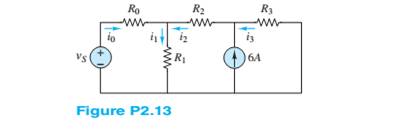
Use KCL to determine the unknown currents in the circuit of Figure P2.13. Assume
Expert Solution & Answer
Want to see the full answer?
Check out a sample textbook solution
Students have asked these similar questions
The circuit shown in Figure P1.75 contains a voltage-controlled current source. Solve for v s.
For the circuit shown in Figure P1.76, solve for i s. What types of sources are present in this circuit?
For the circuit shown in Figure P1.77, solve for the current i x. What types of sources are present in this circuit?
Chapter 2 Solutions
Principles and Applications of Electrical Engineering
Ch. 2 - A free electron has an initial potential energy...Ch. 2 - The units for voltage, current, and resistance are...Ch. 2 - A particular fully charged battery can deliver...Ch. 2 - The charge cycle shown in Figure P2.4 is an...Ch. 2 - Batteries (e.g., lead-acid batteries) store...Ch. 2 - What determines: a. The current through an ideal...Ch. 2 - An automotive battery is rated at 120 A-h. This...Ch. 2 - A car battery kept in storage in the basement...Ch. 2 - Suppose the current through a wire is given by the...Ch. 2 - The charge cycle shown in Figure P2.10 is...
Ch. 2 - The charging scheme used in Figure P2.11 is...Ch. 2 - The charging scheme used in Figure P2.12 is...Ch. 2 - Use KCL to determine the unknown currents in the...Ch. 2 - Use KCL to find the current i1 and i2 in Figure...Ch. 2 - Use KCL to find the current i1,i2, and i3 in the...Ch. 2 - Use KVL to find the voltages v1,v2, and v3 in...Ch. 2 - Use KCL to determine the current i1,i2,i3, and i4...Ch. 2 - In the circuits of Figure P2.18, the directions...Ch. 2 - Find the power delivered by each source in Figure...Ch. 2 - Determine whether each element in Figure P2.20 is...Ch. 2 - In the circuit of Figure P2.21, determine the...Ch. 2 - For the circuit shown in Figure P2.22: a....Ch. 2 - For the circuit shown in Figure P2.23,...Ch. 2 - For the circuit shown in Figure P2.24, determine...Ch. 2 - For the circuit shown in Figure P2.25, determine...Ch. 2 - Prob. 2.26HPCh. 2 - Prob. 2.27HPCh. 2 - Prob. 2.28HPCh. 2 - Prob. 2.29HPCh. 2 - Prob. 2.30HPCh. 2 - Prob. 2.31HPCh. 2 - In the circuit of Figure P2.32, assume v2=vs/6 and...Ch. 2 - Prob. 2.33HPCh. 2 - An incandescent light bulb rated at 100 W will...Ch. 2 - An incandescent lightbulb rated at 60 W...Ch. 2 - Refer to Figure P2.36, and assume that...Ch. 2 - Refer to Figure P2.37, and assume that...Ch. 2 - Refer to Figure P2.38, and assume...Ch. 2 - Prob. 2.39HPCh. 2 - With no load attached, the voltage at the...Ch. 2 - Prob. 2.41HPCh. 2 - For the circuits of Figure P2.42, determine the...Ch. 2 - At an engineering site, a 1-hp motor is placed...Ch. 2 - Cheap resistors are fabricated by depositing a...Ch. 2 - Prob. 2.45HPCh. 2 - Use KCL and Ohm’s law to determine the current...Ch. 2 - Refer to Figure P2.13. Assume R0=1,R1=2,R2=3,R3=4...Ch. 2 - Apply KCL and Ohm’s law to find the power supplied...Ch. 2 - Refer to Figure P2.49 and assume...Ch. 2 - Refer to Figure P2.49 and assume...Ch. 2 - Prob. 2.51HPCh. 2 - The voltage divider network of Figure P2.52 is...Ch. 2 - Find the equivalent resistance seen by the source...Ch. 2 - Find the equivalent resistance seen by the source...Ch. 2 - In the circuit of Figure P2.55, the power absorbed...Ch. 2 - Find the equivalent resistance between terminals...Ch. 2 - For the circuit shown in Figure P2.57, find the...Ch. 2 - For the circuit shown in Figure P2.58,find the...Ch. 2 - Refer to Figure P2.59. Assume...Ch. 2 - Find the equivalent resistance seen by the source...Ch. 2 - For the circuit shown in Figure P2.61. assume...Ch. 2 - Determine the equivalent resistance of the...Ch. 2 - For the circuit shown in Figure P2.58, assume...Ch. 2 - In the circuit of Figure P2.64, find the...Ch. 2 - Refer to Figure P2.64 and determine the equivalent...Ch. 2 - Find the equivalent resistance seen by the source...Ch. 2 - Determine the voltage vo between nodes A and Bin...Ch. 2 - Refer to Figure P2.68 and assume...Ch. 2 - Prob. 2.69HPCh. 2 - Prob. 2.70HPCh. 2 - Prob. 2.71HPCh. 2 - The circuit of Figure P2.72 is used to measure the...Ch. 2 - Consider the practical ammeter, depicted in Figure...Ch. 2 - Prob. 2.74HPCh. 2 - Prob. 2.75HPCh. 2 - Prob. 2.76HPCh. 2 - A voltmeter is used to determine the voltage...Ch. 2 - Prob. 2.78HPCh. 2 - Figure P2.79 shows an aluminum cantilevered beam...Ch. 2 - Refer to Figure P2.79 but assume that the...
Knowledge Booster


Learn more about
Need a deep-dive on the concept behind this application? Look no further. Learn more about this topic, electrical-engineering and related others by exploring similar questions and additional content below.Similar questions
- Consider the circuit shown in Figure P1.64. Use Ohm’s law, KVL, and KCL to find V x.arrow_forwardA practical voltmeter has an internal resistance rm.What is the value of rm if the meter reads 11.81 Vwhen connected as shown in Figure P2.75.arrow_forwardConsider the circuit shown in figure 2-8. the circuit operates at 60 hz, the rms of the voltage is 120 volts, the resistor has a value of 40 ohm, the inductor is 0.1592 H, and the capacitance is 33.16 UF. a) Find the impedance of the inductor and the capacitor. b) Find the current in each leg of the circuit and the total current from the source. c) Draw a phasor diagram showing the source voltage and all the currents. d) Find the total impedance of the RLC parallel combinationarrow_forward
- For the circuit shown in Figure P2.48, find theequivalent resistance seen by the source. How muchpower is delivered by the source?arrow_forwardThe diagram shows an ideal (zero internal resistance) DC source connected to three identical resitances and a switch. In the diagram, the switch is open. If initially, the switch is open, what happens to current I1 and I2 after the switch is closed?arrow_forwardFor the network shown in figure (3), if the switch is closed for 2usec and then opened for Susec, find mathematical expressions for vi and in of both periods of time and then plot the waveforms of vL and i as a function of time.arrow_forward
- In the circuit in the figure, the value of the current I1 is found as ………..Amperes.arrow_forward2.43 Suppose a 12-V voltage source is connected between nodes A and B of the circuit of Figure P2.14, with the posi- tive side at A. Find the magnitude and polarity of the voltage appearing between C and D, as well as the power supplied by the source.arrow_forwardSolve for the other voltages shown in Figure P1.43 given that v a = 5 V, v b = 7 V, v f = -10 V and v h = 6 V.arrow_forward
- lell L1 R Ro 2. In this figure, assume arbitrary numbers for R1, R2, L1, and L2 including some number for the battery E. Find the rate of current in which inductor one (L1) is changing just after the switch is closed. Next, find the current in L1 after some time after the switch has been closed. lellarrow_forward2:34 ull 4G I moodle1.du.edu.om An RTD forms one arm of a Wheatstone bridge as shown in the figure. The RTD is used to measure a temperature with the bridge is operated in a balanced mode. The RTD has a resistance of 252 at a temperature of 0°C and a thermal coefficient of resistance a=0.003925C-1. The value of the variable resistance R, must be set to 41.485 Q to balance the bridge circuit. Determine the temperature measured by the RTD where R2=R3=1002 R2 R3 RTD RRTD E, Select one: O a. 4200arrow_forwardIf the potential of point P in the circuit given in the figure is 100VWhat is the potential of the Q point?arrow_forward
arrow_back_ios
SEE MORE QUESTIONS
arrow_forward_ios
Recommended textbooks for you
 Introductory Circuit Analysis (13th Edition)Electrical EngineeringISBN:9780133923605Author:Robert L. BoylestadPublisher:PEARSON
 Delmar's Standard Textbook Of ElectricityElectrical EngineeringISBN:9781337900348Author:Stephen L. HermanPublisher:Cengage Learning
 Programmable Logic ControllersElectrical EngineeringISBN:9780073373843Author:Frank D. PetruzellaPublisher:McGraw-Hill Education
 Fundamentals of Electric CircuitsElectrical EngineeringISBN:9780078028229Author:Charles K Alexander, Matthew SadikuPublisher:McGraw-Hill Education
 Electric Circuits. (11th Edition)Electrical EngineeringISBN:9780134746968Author:James W. Nilsson, Susan RiedelPublisher:PEARSON
 Engineering ElectromagneticsElectrical EngineeringISBN:9780078028151Author:Hayt, William H. (william Hart), Jr, BUCK, John A.Publisher:Mcgraw-hill Education,
Introductory Circuit Analysis (13th Edition)
Electrical Engineering
ISBN:9780133923605
Author:Robert L. Boylestad
Publisher:PEARSON
Delmar's Standard Textbook Of Electricity
Electrical Engineering
ISBN:9781337900348
Author:Stephen L. Herman
Publisher:Cengage Learning
Programmable Logic Controllers
Electrical Engineering
ISBN:9780073373843
Author:Frank D. Petruzella
Publisher:McGraw-Hill Education
Fundamentals of Electric Circuits
Electrical Engineering
ISBN:9780078028229
Author:Charles K Alexander, Matthew Sadiku
Publisher:McGraw-Hill Education
Electric Circuits. (11th Edition)
Electrical Engineering
ISBN:9780134746968
Author:James W. Nilsson, Susan Riedel
Publisher:PEARSON
Engineering Electromagnetics
Electrical Engineering
ISBN:9780078028151
Author:Hayt, William H. (william Hart), Jr, BUCK, John A.
Publisher:Mcgraw-hill Education,
Lesson 2 - Source Transformations, Part 2 (Engineering Circuits); Author: Math and Science;https://www.youtube.com/watch?v=7gno74RhVGQ;License: Standard Youtube License