
Videos
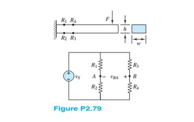
Figure P2.79 shows an aluminum cantilevered beam loaded by the force F. Strain gauges
Want to see the full answer?
Check out a sample textbook solution
Chapter 2 Solutions
Principles and Applications of Electrical Engineering


- DETERMINE AND LABEL THE LOOPS. Solve the missing values of electric currents using Kirchhoff's laws. FInd the value of electric current flowing in and out of junction barrow_forwardWhat is the force F on the 1.0 nC charge in the middle of Figure 2 due to the four other charges? Notice:Give your answer in component form(in x and y components). Along with calculations also write theory to help me understand,i have got stuck with different answers to this question,plz help me answering properly.arrow_forwardUrgent please In the circuit shown in the figure, the RL load is connected to a 20 V source when switch K is in position 1; In this position, draw the waveforms of the welding voltage, the voltage at the R end, the voltage at the L end and the current 1.arrow_forward
- A single strain gauge is bonded to a beam 0.1 m long and has a cross section area 4 cm². Young modulus for steel is 207 GN/m². The strain gauge unstrained resistance of 250 2 and a gauge factor of 2 when a load is applied the resistance of gauge change by 0.013 2. Calculate the change in length of the steel beam and the amount of force applied to the beam.arrow_forwardWhat does a compatible load mean? What if the load is not compatible? -electromagntic wawe theoryarrow_forwardAn ac resistance is higher than a dc resistance. True Falsearrow_forward
- Using the rules for parallel circuits and Ohmslaw, solve for the missing values. ETE1E2E3E4ITl1I2l33.2AI4RT3.582R116R210R3R420PTP1P2P3P4arrow_forwardWhat are interpoles, and what is their purpose?arrow_forwardYou are working as an electrician in a large steel manufacturing plant, and you are in the process of doing preventive maintenance on a large DC generator. You have megged both the series and shunt field windings and found that each has over 10 M to ground. Your ohmmeter, however, indicates a resistance of 1.5 across terminals S1andS2. The ohmmeter indicates a resistance of 225 between terminals F1andF2. Are these readings normal for this type machine, or is there a likely problem? Explain your answer.arrow_forward
- TRUE OR FALSE Ultimate tensile strength has the same value to yield strength in brittle materials. If bulk material is being subjected to tensile stress, slip will occur. In the presence of magnetic field, ferromagnets increase the magnetic flux density. In terms of properties, sandwich panels have isotropic.arrow_forward2:34 ull 4G I moodle1.du.edu.om An RTD forms one arm of a Wheatstone bridge as shown in the figure. The RTD is used to measure a temperature with the bridge is operated in a balanced mode. The RTD has a resistance of 252 at a temperature of 0°C and a thermal coefficient of resistance a=0.003925C-1. The value of the variable resistance R, must be set to 41.485 Q to balance the bridge circuit. Determine the temperature measured by the RTD where R2=R3=1002 R2 R3 RTD RRTD E, Select one: O a. 4200arrow_forwardIn a certain cast-steel core series magnetic circuit with a 400 turns, 170 At/m, mean length of 0.16 m and 0. 002 square meters cross-sectional area. the value of current to develop a 0.0004 Wb isarrow_forward
 Delmar's Standard Textbook Of ElectricityElectrical EngineeringISBN:9781337900348Author:Stephen L. HermanPublisher:Cengage Learning
 Power System Analysis and Design (MindTap Course ...Electrical EngineeringISBN:9781305632134Author:J. Duncan Glover, Thomas Overbye, Mulukutla S. SarmaPublisher:Cengage Learning