
Concept explainers
Videos
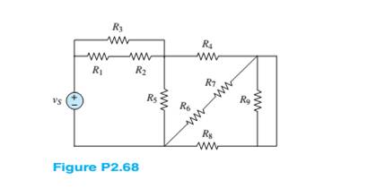
Refer to Figure P2.68 and assume
a. The number of nodes in the circuit.
b. The power delivered by the source
c. The equivalent resistance seen by the source
Want to see the full answer?
Check out a sample textbook solution
Chapter 2 Solutions
Principles and Applications of Electrical Engineering


- consider the following circuit composed of three resistors and two batteries. each resistor has a resistance of 2.00 ohms. assume that the branch currents flow in the directions indicated in the figure. note that: I = 0.600 A I = 0.800 A E1= 10.0V R1= 10 ohms R3= 5 ohms Solve: a.) Write out the equation relating the currents by using the junction rule at node a. Additionally, what is the magnitude of I3? b.) What is the resistance of R2? c.) what is E2?arrow_forwardAn electric circuit with two DC power supplies is shown in Figure A (E1 and E2). Assume that E1 = 200 V, E2 = 120 V, and that all resistors have similar value of R = 20. Using the Superposition theory and the Current Divider Rule, simplify the circuit and determine the current (IR6) across resistor R6.arrow_forwardRefer to the following circuit diagram. Find the current Is1 supplied by source E₁. and current Is2 supplied by E2. E₁ 130V Ist A Z₁ 3352 N Z₂ 1052 B D Z₁ 2402 Z 502 C Isz E₂ 110Varrow_forward
- Vi Ri Vo Il The elements in the circuit shown have the following values: R = 2570.11 N. R2 = 4277.34 N. R3 = 4236.39 N. R4 = 622.17 N. Vị = 102.816373 V. h = 0.0176 A. Determine the following: a.) Using any circuit method you prefer, solve for the voltage V, b.) Determine the current flowing through R4. c.) Determine the magnitude of the current flowing through the resistor R3 (Hint: Assume the current flows up through R3). d.) Determine the power dissipated by R4 (in Watts).arrow_forwardResistors are said to be connected in parallel Select one: a. Circuit elements connected in parallel have the same voltage across their terminals Eion b. All of the answers C. When two circuit elements connect at a single node pair Previous page Next p Jump to... Return to: Generalarrow_forwardThree resistors of 50 N, 100 N and an unknown resistance R are connected in parallel and the combination is connected to a 25 V source. If the total current delivered by the source is 1 A, determine the following: A. The value of R (Ans. R = 100 2) B. The current in each resistor (Ans. I1 = 0.5 A, I2 = I3 = 0.25 A) C. Which resistor dissipates the highest power? Show your solution. (Ans. R1)arrow_forward
- Consider the circuit of resistors shown. Find the equivalent resistance Reg • Find the currents ,...,Is through each resistor and the voltages V1,..,Vs across each resistm Find the total power P dissipated in the circuit. R = 62 R:= 42 R=122 R = 392 R=52 E=12Varrow_forwardDifferentiate between Kirchhoff's Voltage Law and Kirchhoff's Current Law. Support you answer by appropriate example. Debate that how these laws are supportive to solve complex circuits.arrow_forwardMost sources of electrical power behave as (approximately) ideal voltage sources. In this case, if we have several loads that we want to operate independently, we place the loads in parallel with a switch in series with each load. Thereupon, we can switch each load on or off without affecting the power delivered to the other loads. How would we connect the loads and switches if the source is an ideal independent current source? Draw the diagram of the current source and three loads with on–off switches such that each load can be switched on or off without affecting the power supplied to the other loads. To turn a load off, should the corresponding switch be opened or closed? Explain.arrow_forward
- The following are the readings taken while conducting an experiment on a wind turbine. what will be the value of open circuit voltage, if the short circuit current is 0.472 A, Maximum power point voltage is 5.32 V, Maximum power point current is 0.111 A and the fill factor is 0.599? Select one: a. 2080 mV b. 2.08 mV c. 8020 V d. 80.2 Varrow_forwardFind the Power Dissipated in the load resistance R5 (Power of R5) by using the Mesh Current Method. Student numbers from 180207003 up to 180207037 (including) 1=4A Student numbers from 180207039 up to 190207076 (including) 11=1A V1=10 V V1=4 V V1 R2 R4 out1 out2 R3 4. 11 R1 R5 10 B1 1 V=5*V(out1)arrow_forwardSy A circuit design calls a 1.5 kN resistor to have 4.7 V across its terminals. What would be the expected current? The circuit is built, and the resistance is measured at 1500 2 and the voltage at 4.7 V. What is the current through the resistor? f is iearrow_forward
 Introductory Circuit Analysis (13th Edition)Electrical EngineeringISBN:9780133923605Author:Robert L. BoylestadPublisher:PEARSON
 Delmar's Standard Textbook Of ElectricityElectrical EngineeringISBN:9781337900348Author:Stephen L. HermanPublisher:Cengage Learning
 Programmable Logic ControllersElectrical EngineeringISBN:9780073373843Author:Frank D. PetruzellaPublisher:McGraw-Hill Education
 Fundamentals of Electric CircuitsElectrical EngineeringISBN:9780078028229Author:Charles K Alexander, Matthew SadikuPublisher:McGraw-Hill Education
 Electric Circuits. (11th Edition)Electrical EngineeringISBN:9780134746968Author:James W. Nilsson, Susan RiedelPublisher:PEARSON
 Engineering ElectromagneticsElectrical EngineeringISBN:9780078028151Author:Hayt, William H. (william Hart), Jr, BUCK, John A.Publisher:Mcgraw-hill Education,