
Principles and Applications of Electrical Engineering
6th Edition
ISBN: 9780073529592
Author: Giorgio Rizzoni Professor of Mechanical Engineering, James A. Kearns Dr.
Publisher: McGraw-Hill Education
expand_more
expand_more
format_list_bulleted
Concept explainers
Videos
Textbook Question
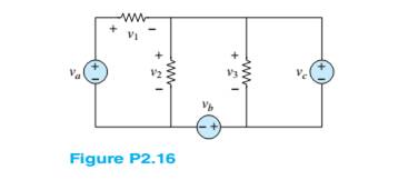
Chapter 2, Problem 2.16HP
Use KVL to find the voltages
Expert Solution & Answer
Want to see the full answer?
Check out a sample textbook solution
Students have asked these similar questions
Given four resistors R1 = 100 ohms, R2=250 ohms, R3 = 350 ohms, and R4 = 200 ohms such that R1 and R2 in parallel will be connected in series with R3 and R4 in parallel. The series-parallel combination is connected across a 24-volt DC power supply. Find the voltage across R2 and voltage across R4
voltage drops across R2 and R4 are both 12 V
voltage drop across R2 is 18.63 V and voltage across R4 is 5.37 V
voltage drop across R2 is 8.63 V and voltage across R4 is 15.37 V
voltage drop across R2 is 8.63 V and voltage across R4 is 15.37 V
answer as soon
C) Figure Q2(c) shows a simple electronic circuit. A recently graduated engineering student from eau has been tasked by his Senior Engineer to determine the equivalent circuit between Terminal A and B. Please help him to analyze and find the equivalent resistance using delta-wye transformation
Most sources of electrical power behave as (approximately) ideal voltage sources. In this case, if we have several loads that we want to operate independently, we place the loads in parallel with a switch in series with each load. Thereupon, we can switch each load on or off without affecting the power delivered to the other loads. How would we connect the loads and switches if the source is an ideal independent current source? Draw the diagram of the current source and three loads with on–off switches such that each load can be switched on or off without affecting the power supplied to the other loads. To turn a load off, should the corresponding switch be opened or closed? Explain.
Chapter 2 Solutions
Principles and Applications of Electrical Engineering
Ch. 2 - A free electron has an initial potential energy...Ch. 2 - The units for voltage, current, and resistance are...Ch. 2 - A particular fully charged battery can deliver...Ch. 2 - The charge cycle shown in Figure P2.4 is an...Ch. 2 - Batteries (e.g., lead-acid batteries) store...Ch. 2 - What determines: a. The current through an ideal...Ch. 2 - An automotive battery is rated at 120 A-h. This...Ch. 2 - A car battery kept in storage in the basement...Ch. 2 - Suppose the current through a wire is given by the...Ch. 2 - The charge cycle shown in Figure P2.10 is...
Ch. 2 - The charging scheme used in Figure P2.11 is...Ch. 2 - The charging scheme used in Figure P2.12 is...Ch. 2 - Use KCL to determine the unknown currents in the...Ch. 2 - Use KCL to find the current i1 and i2 in Figure...Ch. 2 - Use KCL to find the current i1,i2, and i3 in the...Ch. 2 - Use KVL to find the voltages v1,v2, and v3 in...Ch. 2 - Use KCL to determine the current i1,i2,i3, and i4...Ch. 2 - In the circuits of Figure P2.18, the directions...Ch. 2 - Find the power delivered by each source in Figure...Ch. 2 - Determine whether each element in Figure P2.20 is...Ch. 2 - In the circuit of Figure P2.21, determine the...Ch. 2 - For the circuit shown in Figure P2.22: a....Ch. 2 - For the circuit shown in Figure P2.23,...Ch. 2 - For the circuit shown in Figure P2.24, determine...Ch. 2 - For the circuit shown in Figure P2.25, determine...Ch. 2 - Prob. 2.26HPCh. 2 - Prob. 2.27HPCh. 2 - Prob. 2.28HPCh. 2 - Prob. 2.29HPCh. 2 - Prob. 2.30HPCh. 2 - Prob. 2.31HPCh. 2 - In the circuit of Figure P2.32, assume v2=vs/6 and...Ch. 2 - Prob. 2.33HPCh. 2 - An incandescent light bulb rated at 100 W will...Ch. 2 - An incandescent lightbulb rated at 60 W...Ch. 2 - Refer to Figure P2.36, and assume that...Ch. 2 - Refer to Figure P2.37, and assume that...Ch. 2 - Refer to Figure P2.38, and assume...Ch. 2 - Prob. 2.39HPCh. 2 - With no load attached, the voltage at the...Ch. 2 - Prob. 2.41HPCh. 2 - For the circuits of Figure P2.42, determine the...Ch. 2 - At an engineering site, a 1-hp motor is placed...Ch. 2 - Cheap resistors are fabricated by depositing a...Ch. 2 - Prob. 2.45HPCh. 2 - Use KCL and Ohm’s law to determine the current...Ch. 2 - Refer to Figure P2.13. Assume R0=1,R1=2,R2=3,R3=4...Ch. 2 - Apply KCL and Ohm’s law to find the power supplied...Ch. 2 - Refer to Figure P2.49 and assume...Ch. 2 - Refer to Figure P2.49 and assume...Ch. 2 - Prob. 2.51HPCh. 2 - The voltage divider network of Figure P2.52 is...Ch. 2 - Find the equivalent resistance seen by the source...Ch. 2 - Find the equivalent resistance seen by the source...Ch. 2 - In the circuit of Figure P2.55, the power absorbed...Ch. 2 - Find the equivalent resistance between terminals...Ch. 2 - For the circuit shown in Figure P2.57, find the...Ch. 2 - For the circuit shown in Figure P2.58,find the...Ch. 2 - Refer to Figure P2.59. Assume...Ch. 2 - Find the equivalent resistance seen by the source...Ch. 2 - For the circuit shown in Figure P2.61. assume...Ch. 2 - Determine the equivalent resistance of the...Ch. 2 - For the circuit shown in Figure P2.58, assume...Ch. 2 - In the circuit of Figure P2.64, find the...Ch. 2 - Refer to Figure P2.64 and determine the equivalent...Ch. 2 - Find the equivalent resistance seen by the source...Ch. 2 - Determine the voltage vo between nodes A and Bin...Ch. 2 - Refer to Figure P2.68 and assume...Ch. 2 - Prob. 2.69HPCh. 2 - Prob. 2.70HPCh. 2 - Prob. 2.71HPCh. 2 - The circuit of Figure P2.72 is used to measure the...Ch. 2 - Consider the practical ammeter, depicted in Figure...Ch. 2 - Prob. 2.74HPCh. 2 - Prob. 2.75HPCh. 2 - Prob. 2.76HPCh. 2 - A voltmeter is used to determine the voltage...Ch. 2 - Prob. 2.78HPCh. 2 - Figure P2.79 shows an aluminum cantilevered beam...Ch. 2 - Refer to Figure P2.79 but assume that the...
Knowledge Booster


Learn more about
Need a deep-dive on the concept behind this application? Look no further. Learn more about this topic, electrical-engineering and related others by exploring similar questions and additional content below.Similar questions
- Two resistors A and B are connected in series with a 220-V DC source. a voltmeter with an internal resistance of 10k Ohms is connected across resistor A, the instrument reads 100V and when connected across resistor B, it reads 80V. Find the value of the two resistances in series. please show complete solution.arrow_forwardEлample (1) For the series-parallel arrangement shown in Figure below, find: a) The supply current. I ?. b) The current flowing through each resistor. c) The p.d. across each resistor. R3 2.50 40 Ri R4 RE I ? 200Varrow_forwardIn the figure the current in resistance 6 is i = 1.43 A and the resistances are R₁ = R₂ = R3 = 1.68 2, R₂ = 15.1 Q2, R5 = 7.41 Q2, and R6 = 4.57 2. What is the emf of the ideal battery? E www R₁ O a. 25.7V O b. 52.3 V O C. 47.2 V O d. 21.4 V O e. 6.54 V R3 www R₂ www R₁ R₂ 16 R6arrow_forward
- 2:34 ull 4G I moodle1.du.edu.om An RTD forms one arm of a Wheatstone bridge as shown in the figure. The RTD is used to measure a temperature with the bridge is operated in a balanced mode. The RTD has a resistance of 252 at a temperature of 0°C and a thermal coefficient of resistance a=0.003925C-1. The value of the variable resistance R, must be set to 41.485 Q to balance the bridge circuit. Determine the temperature measured by the RTD where R2=R3=1002 R2 R3 RTD RRTD E, Select one: O a. 4200arrow_forwardA load of 100 ohms is connected to a 200-V source through a wire having a total resistance of 3 ohms. Determine the power lost due to the resistance of the wire.arrow_forwardThe voltage source V1= 250 V with internal resistance R1= 2ohm in Figure 2.1 will feed the RL resistor with a transformer with a conversion ratio of 1/16 and considered ideal. What should be the value (RL) of the RL resistor to be placed so that the RL resistor can draw maximum power from the voltage source? What is the power (Pvi) consumed by the voltage source when the RL resistor you found is active? In this case, how much power (Pri) is spent on the internal resistance of the source, the resistor R1?RL=Pv=PRI =arrow_forward
- 8. Take that vs = 36 V Find the value of i1 in the figure. Find the value of i2 in the figure. .arrow_forwardlo R1 CR2 V alx ........ Figure Q2(b) : Two Closed Loops Circuit (i) Explain the steps required in supermesh analysis for Figure Q2(b). (ii) Determine the mesh currents using the Kirchhoff's Current Law (KCL) and Kirchhoff's Voltage Law (KVL) for Figure Q2(b).arrow_forwardBasic Electrical EngineeringDraw symbols of electrical components. Note: You may use both IEC and NEMA symbols. - Conductors crossing but not connected- Conductors crossing and connected - DC source other than battery- DC generator- AC voltage source- Ideal current source- Ideal Voltage Source- Current Controlled Current Source- Current Controlled Voltage Source- Voltage Controlled Current Source - Voltage Controlled Voltage Sourcearrow_forward
- The voltage across the 16-ohm resistor in the circuit is 80 V, positive at the upper terminal.a. Find the power dissipated in each resistorb. Find the power supplied by the 125 V ideal voltage sourcearrow_forwardSolve for i1 in Figure P2.34 by using superposition.arrow_forwardFind the potential difference between point a and point b for the situation shown below. Here ₁ = 12.0 V, E₂ = 8.77 V and R₁ = 4.13, R₂ = 5.44 , and R3 = 2.28 0. Va - Vb = R₂ V R3 R₁ Warrow_forward
arrow_back_ios
SEE MORE QUESTIONS
arrow_forward_ios
Recommended textbooks for you
 Introductory Circuit Analysis (13th Edition)Electrical EngineeringISBN:9780133923605Author:Robert L. BoylestadPublisher:PEARSON
 Delmar's Standard Textbook Of ElectricityElectrical EngineeringISBN:9781337900348Author:Stephen L. HermanPublisher:Cengage Learning
 Programmable Logic ControllersElectrical EngineeringISBN:9780073373843Author:Frank D. PetruzellaPublisher:McGraw-Hill Education
 Fundamentals of Electric CircuitsElectrical EngineeringISBN:9780078028229Author:Charles K Alexander, Matthew SadikuPublisher:McGraw-Hill Education
 Electric Circuits. (11th Edition)Electrical EngineeringISBN:9780134746968Author:James W. Nilsson, Susan RiedelPublisher:PEARSON
 Engineering ElectromagneticsElectrical EngineeringISBN:9780078028151Author:Hayt, William H. (william Hart), Jr, BUCK, John A.Publisher:Mcgraw-hill Education,
Introductory Circuit Analysis (13th Edition)
Electrical Engineering
ISBN:9780133923605
Author:Robert L. Boylestad
Publisher:PEARSON
Delmar's Standard Textbook Of Electricity
Electrical Engineering
ISBN:9781337900348
Author:Stephen L. Herman
Publisher:Cengage Learning
Programmable Logic Controllers
Electrical Engineering
ISBN:9780073373843
Author:Frank D. Petruzella
Publisher:McGraw-Hill Education
Fundamentals of Electric Circuits
Electrical Engineering
ISBN:9780078028229
Author:Charles K Alexander, Matthew Sadiku
Publisher:McGraw-Hill Education
Electric Circuits. (11th Edition)
Electrical Engineering
ISBN:9780134746968
Author:James W. Nilsson, Susan Riedel
Publisher:PEARSON
Engineering Electromagnetics
Electrical Engineering
ISBN:9780078028151
Author:Hayt, William H. (william Hart), Jr, BUCK, John A.
Publisher:Mcgraw-hill Education,
Why HIGH VOLTAGE DC power Transmission; Author: ElectroBOOM;https://www.youtube.com/watch?v=DFQG9kuXSxg;License: Standard Youtube License