
Principles and Applications of Electrical Engineering
6th Edition
ISBN: 9780073529592
Author: Giorgio Rizzoni Professor of Mechanical Engineering, James A. Kearns Dr.
Publisher: McGraw-Hill Education
expand_more
expand_more
format_list_bulleted
Videos
Textbook Question
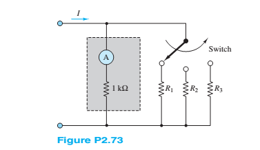
Chapter 2, Problem 2.73HP
Consider the practical ammeter, depicted in Figure P2.73. consisting of an ideal ammeter in series with a
Expert Solution & Answer
Want to see the full answer?
Check out a sample textbook solution
Students have asked these similar questions
4
1.0 k
VS2
VSI
25 V
8 V
Diodes D1 and D2 in the figure are assumed ideal, what is the current through the diodes? *
D₁
B
R
www
C
В-
for the
circuit
shown
in
figure
2, the
resistance of both diodes is 7 0. In the practical model of the diode, determine the current through the
resistor RI when:
• Switch Si is ON and switch S2 is OFF
• Switch Si is OFF and switch S2 is ON
S1
D
S2
D2
Figure 2
v2
10 v
R1
850 0
V3
A dc voltmeter has a sensitivity of 1000 92/V. When it measures half full scale in 100 V
range, the current through the voltmeter is?
Chapter 2 Solutions
Principles and Applications of Electrical Engineering
Ch. 2 - A free electron has an initial potential energy...Ch. 2 - The units for voltage, current, and resistance are...Ch. 2 - A particular fully charged battery can deliver...Ch. 2 - The charge cycle shown in Figure P2.4 is an...Ch. 2 - Batteries (e.g., lead-acid batteries) store...Ch. 2 - What determines: a. The current through an ideal...Ch. 2 - An automotive battery is rated at 120 A-h. This...Ch. 2 - A car battery kept in storage in the basement...Ch. 2 - Suppose the current through a wire is given by the...Ch. 2 - The charge cycle shown in Figure P2.10 is...
Ch. 2 - The charging scheme used in Figure P2.11 is...Ch. 2 - The charging scheme used in Figure P2.12 is...Ch. 2 - Use KCL to determine the unknown currents in the...Ch. 2 - Use KCL to find the current i1 and i2 in Figure...Ch. 2 - Use KCL to find the current i1,i2, and i3 in the...Ch. 2 - Use KVL to find the voltages v1,v2, and v3 in...Ch. 2 - Use KCL to determine the current i1,i2,i3, and i4...Ch. 2 - In the circuits of Figure P2.18, the directions...Ch. 2 - Find the power delivered by each source in Figure...Ch. 2 - Determine whether each element in Figure P2.20 is...Ch. 2 - In the circuit of Figure P2.21, determine the...Ch. 2 - For the circuit shown in Figure P2.22: a....Ch. 2 - For the circuit shown in Figure P2.23,...Ch. 2 - For the circuit shown in Figure P2.24, determine...Ch. 2 - For the circuit shown in Figure P2.25, determine...Ch. 2 - Prob. 2.26HPCh. 2 - Prob. 2.27HPCh. 2 - Prob. 2.28HPCh. 2 - Prob. 2.29HPCh. 2 - Prob. 2.30HPCh. 2 - Prob. 2.31HPCh. 2 - In the circuit of Figure P2.32, assume v2=vs/6 and...Ch. 2 - Prob. 2.33HPCh. 2 - An incandescent light bulb rated at 100 W will...Ch. 2 - An incandescent lightbulb rated at 60 W...Ch. 2 - Refer to Figure P2.36, and assume that...Ch. 2 - Refer to Figure P2.37, and assume that...Ch. 2 - Refer to Figure P2.38, and assume...Ch. 2 - Prob. 2.39HPCh. 2 - With no load attached, the voltage at the...Ch. 2 - Prob. 2.41HPCh. 2 - For the circuits of Figure P2.42, determine the...Ch. 2 - At an engineering site, a 1-hp motor is placed...Ch. 2 - Cheap resistors are fabricated by depositing a...Ch. 2 - Prob. 2.45HPCh. 2 - Use KCL and Ohm’s law to determine the current...Ch. 2 - Refer to Figure P2.13. Assume R0=1,R1=2,R2=3,R3=4...Ch. 2 - Apply KCL and Ohm’s law to find the power supplied...Ch. 2 - Refer to Figure P2.49 and assume...Ch. 2 - Refer to Figure P2.49 and assume...Ch. 2 - Prob. 2.51HPCh. 2 - The voltage divider network of Figure P2.52 is...Ch. 2 - Find the equivalent resistance seen by the source...Ch. 2 - Find the equivalent resistance seen by the source...Ch. 2 - In the circuit of Figure P2.55, the power absorbed...Ch. 2 - Find the equivalent resistance between terminals...Ch. 2 - For the circuit shown in Figure P2.57, find the...Ch. 2 - For the circuit shown in Figure P2.58,find the...Ch. 2 - Refer to Figure P2.59. Assume...Ch. 2 - Find the equivalent resistance seen by the source...Ch. 2 - For the circuit shown in Figure P2.61. assume...Ch. 2 - Determine the equivalent resistance of the...Ch. 2 - For the circuit shown in Figure P2.58, assume...Ch. 2 - In the circuit of Figure P2.64, find the...Ch. 2 - Refer to Figure P2.64 and determine the equivalent...Ch. 2 - Find the equivalent resistance seen by the source...Ch. 2 - Determine the voltage vo between nodes A and Bin...Ch. 2 - Refer to Figure P2.68 and assume...Ch. 2 - Prob. 2.69HPCh. 2 - Prob. 2.70HPCh. 2 - Prob. 2.71HPCh. 2 - The circuit of Figure P2.72 is used to measure the...Ch. 2 - Consider the practical ammeter, depicted in Figure...Ch. 2 - Prob. 2.74HPCh. 2 - Prob. 2.75HPCh. 2 - Prob. 2.76HPCh. 2 - A voltmeter is used to determine the voltage...Ch. 2 - Prob. 2.78HPCh. 2 - Figure P2.79 shows an aluminum cantilevered beam...Ch. 2 - Refer to Figure P2.79 but assume that the...
Knowledge Booster


Learn more about
Need a deep-dive on the concept behind this application? Look no further. Learn more about this topic, electrical-engineering and related others by exploring similar questions and additional content below.Similar questions
- multirange ammeter was designed using direct method to give three scales with Rsh1= 0.001285989 0, Rsh2=0.000562552 0, and Rsh3=0.000100001 Q. The d'Arsonval meter has Rm=6 Q and full scale current of 1.5 mA. Find the ranges.? 8 (Ctrl) -arrow_forwardFor the circuit below, determine the resistor voltage. The source is 5 volts, the Zener potential is 5.2 volts and the resistor is 1k ohms.arrow_forwardFor the circuit below, determine the resistor voltage. The source is 6 volts, the Zener potential is 5.1 volts and the resistor is 1k.arrow_forward
- Sketch the i versus v curve for the following (the voltages beside Zener diodes represents their Zener voltages): i (a) (b) X 2 + 2 Ć V₂=5.6V S.6V 5-6varrow_forwardii. The controlled single-phase rectifier full-wave bridge rectifier of Figure ii has an RL load with R = 25N and L = 50mH. The source is 240 V rms at 60 Hz. Determine the average load current for a = 15° and a = 750 R v, (@t) = Vm sin(@t)\ Vo L ww allarrow_forwardFind the Total current flowing through D1 and D2 and D3. Vs= 10v, R1=R2=R3=10kNThe three diodes are silicon. IS ov R1 D2 R2 D3 SI R4 10k R3arrow_forward
- D. , D2 A R2 200 Q 100HZ C1 R1 R3 D4 D3 8 µF 2 kQ 3 kQ D Answer the following questions, since the minimum voltage value to transmit the zener diode in the figure given above is 9V and the power of this Zener diode is 0.3 watts. a) Enter the name of the circuit in the figure. b) What are the diodes/diodes in positive half-loop transmission?arrow_forwardIn the circuit in the figure, D1 diode is made of silicon D2 diode and germanium. Calculate the induced voltage above a 3 kiloohm resistor?arrow_forwardOhm's law is not applicable to Semiconductors D.C. circuits Small resistors O High currentsarrow_forward
- The single-phase bridge rectifier of Figure below is required to supply an average voltage io of Vdc = 300 V to a resistive load of R = 15 2. Determine the voltage and current ratings of diodes and transformer. D₁ D₂ D3 D₂ www voarrow_forwardii. The controlled single-phase rectifier full-wave bridge rectifier of Figure ii has an RL load with R = 252 and L = 50mH. The source is 240 V rms at 60 Hz. Determine 15° and a = 750 the average load current for a = v, (or) = Vm sin(or) Figure 2: For part (c) iiarrow_forwardWhen resistors with higher wattage ratings are required, resistors are generally used to dissipate the excessive heat. a) Variable b) Fixed c) Wirewound d) Preset The diode is considered shorted when both anode and cathode has a) Low resistance b) High resistance c) Different resistance d) None of the above When two resistors are connected in parallel then their overall power rating is a) Increased b) Decreased c) Doubled d) Reducedarrow_forward
arrow_back_ios
SEE MORE QUESTIONS
arrow_forward_ios
Recommended textbooks for you
 Introductory Circuit Analysis (13th Edition)Electrical EngineeringISBN:9780133923605Author:Robert L. BoylestadPublisher:PEARSON
 Delmar's Standard Textbook Of ElectricityElectrical EngineeringISBN:9781337900348Author:Stephen L. HermanPublisher:Cengage Learning
 Programmable Logic ControllersElectrical EngineeringISBN:9780073373843Author:Frank D. PetruzellaPublisher:McGraw-Hill Education
 Fundamentals of Electric CircuitsElectrical EngineeringISBN:9780078028229Author:Charles K Alexander, Matthew SadikuPublisher:McGraw-Hill Education
 Electric Circuits. (11th Edition)Electrical EngineeringISBN:9780134746968Author:James W. Nilsson, Susan RiedelPublisher:PEARSON
 Engineering ElectromagneticsElectrical EngineeringISBN:9780078028151Author:Hayt, William H. (william Hart), Jr, BUCK, John A.Publisher:Mcgraw-hill Education,
Introductory Circuit Analysis (13th Edition)
Electrical Engineering
ISBN:9780133923605
Author:Robert L. Boylestad
Publisher:PEARSON
Delmar's Standard Textbook Of Electricity
Electrical Engineering
ISBN:9781337900348
Author:Stephen L. Herman
Publisher:Cengage Learning
Programmable Logic Controllers
Electrical Engineering
ISBN:9780073373843
Author:Frank D. Petruzella
Publisher:McGraw-Hill Education
Fundamentals of Electric Circuits
Electrical Engineering
ISBN:9780078028229
Author:Charles K Alexander, Matthew Sadiku
Publisher:McGraw-Hill Education
Electric Circuits. (11th Edition)
Electrical Engineering
ISBN:9780134746968
Author:James W. Nilsson, Susan Riedel
Publisher:PEARSON
Engineering Electromagnetics
Electrical Engineering
ISBN:9780078028151
Author:Hayt, William H. (william Hart), Jr, BUCK, John A.
Publisher:Mcgraw-hill Education,
Lesson 2 - Source Transformations, Part 2 (Engineering Circuits); Author: Math and Science;https://www.youtube.com/watch?v=7gno74RhVGQ;License: Standard Youtube License