
Concept explainers
Videos
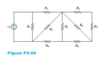
Find the equivalent resistance seen by the source in Figure P2.60. How many nodes are in the circuit?
Assume
Want to see the full answer?
Check out a sample textbook solution
Chapter 2 Solutions
Principles and Applications of Electrical Engineering


- 9. The circuit shown in the figure is an example of a voltage divider. The potential difference ɛ is divided by R1 and R2, and only a fraction of the voltage appears across the load resistor, RL. Calculate the value of R2 so that the voltage across Rį is 4 V when ɛ = 20 V, R1 = 80 n and R, = 600 N. R2arrow_forwardElectrical Engineering SOLVE BOTHB AND C PARTS PLS. UPVOTE GUARANTEED. b Calculate below resistance values and re-draw below circuit by showing numeric resistance values. R1 = TO T=44 R2 = 4T Q solve both b and c parts pls R3 = 8T Q R4 = 16T Q Ry = 20T Q V; O R1 R2 V. R4 Express vo in terms of v, and calculate the gain of the circuit A =arrow_forwardTwo batteries are connected in parallel delivering power to a power resistor. The first battery has an open circuit voltage of 12.6 V and an internal resistance of 0.2 ohm. The second battery has an open circuit voltage of 12.2 V and an internal resistance of 0.3 ohm. Find the maximum power delivered to the load resistance.arrow_forward
- Q2/ Determine the value of R and current through it in following Figure, if current through branch AO * ?is zero 10 V D. R = 1 0,1 = 3.5A. O C. R = 30,1 = 4.5A. O A.R = 40,1 = 3.5A. B. R = 2 0,1 = 2.5A. Oarrow_forwardRefer to the following circuit diagram. Find the current Is1 supplied by source E₁. and current Is2 supplied by E2. E₁ 130V Ist A Z₁ 3352 N Z₂ 1052 B D Z₁ 2402 Z 502 C Isz E₂ 110Varrow_forwardA variable resistive load has a 10-10092 range, and is connected across the load terminals of a circuit. This circuit has a Thevenin voltage and resistance of 150 V and 25 2, respectively. What should be the resistance of the variable resistive load so that it will consume 80% of the max power that this circuit can deliver? (Round-off to two decimal places)arrow_forward
- Each of the cells shown in the figure has an emf of 1.50 V and a 0.0750-ohm internalresistance. Find I1, I2, and I3.arrow_forwardCAN YOU SOLVE THIS QUICKLTY In the circuit shown in the figure, OPAMP is fed from a 15 V source. VS voltage applied to the input of the circuitPlot the VO change depending on the change.arrow_forwardI want the solution Q2/ Q3/ Q4/arrow_forward
- 1. Using Series-Parallel concept, Find the following for the given circuit. The value of the power supply and resistances are given in Page-4. a) the current supplied by the source b) the voltage drops across each resistor c) the r dissipated by R3 R1=45kn R2=2kn R3=22kQ R4=14kn R5=17kn R6=85kn V1=24 v R₁ R₂ V₁ R₂ R₂ R₂arrow_forwardb) The circuit in Figure Q2(b) is referred. i. Show the supernode in the circuit. Explain the reason for your answer. ii. By using nodal analysis with supernode, solve for the node voltages at each assigned nodes in the circuit. 2 A 12 V Figure Q2(b)arrow_forwardUse the Principle of Superposition to determine the current i through R3 in the Figure. Let R1 = 100, R2 = 40, R3 = 20, R4 = 20, R5= 20, Vs 10 V, Is = 2A. ww VS R3 ww wwwarrow_forward
 Introductory Circuit Analysis (13th Edition)Electrical EngineeringISBN:9780133923605Author:Robert L. BoylestadPublisher:PEARSON
 Delmar's Standard Textbook Of ElectricityElectrical EngineeringISBN:9781337900348Author:Stephen L. HermanPublisher:Cengage Learning
 Programmable Logic ControllersElectrical EngineeringISBN:9780073373843Author:Frank D. PetruzellaPublisher:McGraw-Hill Education
 Fundamentals of Electric CircuitsElectrical EngineeringISBN:9780078028229Author:Charles K Alexander, Matthew SadikuPublisher:McGraw-Hill Education
 Electric Circuits. (11th Edition)Electrical EngineeringISBN:9780134746968Author:James W. Nilsson, Susan RiedelPublisher:PEARSON
 Engineering ElectromagneticsElectrical EngineeringISBN:9780078028151Author:Hayt, William H. (william Hart), Jr, BUCK, John A.Publisher:Mcgraw-hill Education,