
Concept explainers
Videos
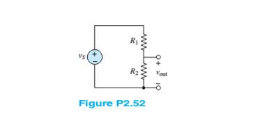
The voltage divider network of Figure P2.52 is designed to provide
a. 1f the resistors have
b. Find the expected output voltage range for a tolerance of
Want to see the full answer?
Check out a sample textbook solution
Chapter 2 Solutions
Principles and Applications of Electrical Engineering


- What is the load current for the circuit shown in the figure? Please choose one: a. 9.0 mA b. 7.5 mA c. 3.0 mA D. 6.0 mAarrow_forwardQUESTION 2 a) b) Figure Q2a shows a parallel clipper circuit. Analyze the circuit and hence sketch the output waveform for one complete cycle of the input. R own V₁ 10 Vi (V) A -20 15- -15 t(s) t(s) Figure Q2a Determine the output voltage, V, and hence sketch the output voltage waveform for the clamper circuit shown in Figure Q2b. C Figure Q2b Si Si 5 V 3V V₂ R Voarrow_forwardFor the given resistor combination circuit, determine (a) the equivalent resistance (show simplification of circuits), (b) the current demanded from the 15V voltage source (neglecting internal resistance), (c) the potential drop across each resistor, and (d) the current across each resistor.arrow_forward
- Q1) For the circuits shown in figure below, obtain the equivalent resistance at terminals a-b. 200 wwarrow_forward100 150 + VA- a + -7V, 81. 52 Figure 2 shows a simplified model of a gas-discharge lamp. One characteristic of these lamps is that they exhibit negative resistance; in other words, as current increases the voltage drops further, making such lamps inherently unstable. As such, a current-limiting ballast is required. For the connection shown in the figure: 1. Find the equivalent Thevenin circuit of the lamp. 2. Find the ballast resistance needed to limit the current drawn from a 24-volt source to 6 amperes.arrow_forwardHome Work: P1 Two resistors must be selected so that the current in one is four times the current in the other. If.. their equivalent parallel resistance is 5kr, calculate R and R₂.. Ans: 6.25k,25k]arrow_forward
- Tutorial Problems As 1. For the circuit in Figure, find (a) 80a 200 100 fthe value of the supply voltage V (b) the value of currentarrow_forward1. A VBE multiplier (see Figure 1) is designed with equal resistances for operation at bias current of 1 mA with half current flowing in the bias network. The initial design is based on B=0 and VBE=0.7V at 1 mA. Find the required resistor values and the biasing voltage VBB. You can assume that VBE is 0.7V for all currents (constant voltage drop model) +Vcc IBIAS R2 VBB RL -Vcc Figure 1. A class AB output stage utilizing a VBEmultiplier for biasingarrow_forwardFor the circuit shown in Figure Q2ai, drain current In is 2.26 mA and drain to source voltage VDs is 5.22V. Calculate the values of VDD and VD? Q2ai) VDD RD 2kQ •VD Q1 RG ς1 2ΜΩ RS 1kQ Figure Q2aiarrow_forward
- Three resistors of 50 N, 100 N and an unknown resistance R are connected in parallel and the combination is connected to a 25 V source. If the total current delivered by the source is 1 A, determine the following: A. The value of R (Ans. R = 100 2) B. The current in each resistor (Ans. I1 = 0.5 A, I2 = I3 = 0.25 A) C. Which resistor dissipates the highest power? Show your solution. (Ans. R1)arrow_forwardSy A circuit design calls a 1.5 kN resistor to have 4.7 V across its terminals. What would be the expected current? The circuit is built, and the resistance is measured at 1500 2 and the voltage at 4.7 V. What is the current through the resistor? f is iearrow_forwardWhat is the zener current for the circuit shown? Please choose one: a. 6.0 mA b. 9.0 mA c. 7.5 mA D. 3.0 mAarrow_forward
 Introductory Circuit Analysis (13th Edition)Electrical EngineeringISBN:9780133923605Author:Robert L. BoylestadPublisher:PEARSON
 Delmar's Standard Textbook Of ElectricityElectrical EngineeringISBN:9781337900348Author:Stephen L. HermanPublisher:Cengage Learning
 Programmable Logic ControllersElectrical EngineeringISBN:9780073373843Author:Frank D. PetruzellaPublisher:McGraw-Hill Education
 Fundamentals of Electric CircuitsElectrical EngineeringISBN:9780078028229Author:Charles K Alexander, Matthew SadikuPublisher:McGraw-Hill Education
 Electric Circuits. (11th Edition)Electrical EngineeringISBN:9780134746968Author:James W. Nilsson, Susan RiedelPublisher:PEARSON
 Engineering ElectromagneticsElectrical EngineeringISBN:9780078028151Author:Hayt, William H. (william Hart), Jr, BUCK, John A.Publisher:Mcgraw-hill Education,