
Videos
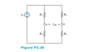
Refer to Figure P2.36, and assume that
a. The voltage
b. The power dissipated in
Want to see the full answer?
Check out a sample textbook solution
Chapter 2 Solutions
Principles and Applications of Electrical Engineering


- The circuit below(left) displays a schematic diagram of a battery. The voltage measured by U1 is called the terminal voltage given R1 = 1 ohm. In the circuit below(right), the terminal voltage of each of the battery-resistor combination is VT = 1.5 volts. Find The power dissipated by the internal resistance R1. The power dissipated by R5 if R1 = R2 = R3 = R4 = 0arrow_forwardP2.84. Find the Thévenin and Norton equivalent circuits for the circuit shown in Figure P2.84 O. Take care that you orient the polarity of the voltage source and the direction of the current source correctly relative to terminals a and b. What effect does the 7 – N resistor have on the equivalent circuits? Explain your answer. 1 A 48 N 12 V 16 Narrow_forwardGiven the circuit of Figure (1), find the following quantities: a. Total resistance, RT b. Voltages V2 and V4 c. Currents IT, I1, and 12 R2 = 4 k2 C V2 11 I2 R3 3 kQ R4 V4 R1 6 k2 15 k2 E = 45 V IT Q + Page 1arrow_forward
- The circuit below(left) displays a schematic diagram of a battery. The voltage measured by U1 is called the terminal voltage given R1 = 1 ohm. In the circuit below(right), the terminal voltage of each of the battery-resistor combination is VT = 1.5 volts. Find -The power dissipated by the internal resistance R1. -The power dissipated by R5 if R1 = R2 = R3 = R4 = 0-The percentage of power dissipation loss due to the four resistors R1, R2, R3, and R4.arrow_forwardThe figure below shows resistors wired in a combination of series and parallel. (a) Find the equivalent resistance of the circuit. (b) What is the potential drop V1 across resistor R1? (c) Find the current I2 through resistor R2. (d) What power is dissipated by R2?arrow_forwardSy A circuit design calls a 1.5 kN resistor to have 4.7 V across its terminals. What would be the expected current? The circuit is built, and the resistance is measured at 1500 2 and the voltage at 4.7 V. What is the current through the resistor? f is iearrow_forward
- Q1: Use a qualitative analysis to identify the filter type for the circuit shown in Figure-1 below. Hence use a quantitative analysis to calculate its parameters. Vin L Vout Figure 1arrow_forwardA combination of three resistors R1, R2 and R3 in series is connected across a voltage source Vr. The voltage drop across R1 and R3 are 10 V and 36 V, respectively. If the current supplied by the source voltage is 1.4 A and the total power supplied by the source is 70 W, Calculate the following: A. The value of Vr and the voltage drop across R2 (Ans. VT B. The equivalent resistance across the voltage source, and the values of R1, R2 and R3 (Ans. Req 50 V, V2 = 4 V) 2.8571 N, R3 = 35.7143 N, R¡ = 7.1429 N, R2 = C. The power dissipated by each resistor (Ans. P1 = 14 W, P2 = 5.6 W, P3 = 50.4 W) = 25.7143 N)arrow_forwardRefer to the figure. Given 2RR R2 = 3R2 - RL a) Design the power supply circuit so that y = 3v,when R,-600 Q. by Assume input voltage is 180 V. Which resistor in the circuit dissipates the most power? What is the power? c) Which resistor dissipates the least power? What is the power? R2 ww R ww I RL 14. ww- 年 wwarrow_forward
- 2.23 Refer to Figure P2.23. Assume vs = 20 V, R₁ = 10 S2, R₂ = 5 2, R₂ = 892, R₁ = 2 S2, R₁ = 4 S2, R6 = 2 S2, R₁ = 1 92, and Rg = 10 52. How many nodes are in the circuit? a. Determine the equivalent resistance seen by the voltage source vs. b. Apply voltage division to find the voltage across R₁ and Rg. VS R₂ ww R₁ Figure P2.23 www R3 Rs R₁3 R6 ww R$2 www R₁arrow_forwardDifferentiate between Kirchhoff's Voltage Law and Kirchhoff's Current Law. Support you answer by appropriate example. Debate that how these laws are supportive to solve complex circuits.arrow_forwardThe circuit below(left) displays a schematic diagram of a battery. The voltage measured by U1 is called the terminal voltage given R1 = 1 ohm. In the circuit below(right), the terminal voltage of each of the battery-resistor combination is VT = 1.5 volts. Find The percentage of power dissipation loss due to the four resistors R1, R2, R3, and R4.arrow_forward
 Introductory Circuit Analysis (13th Edition)Electrical EngineeringISBN:9780133923605Author:Robert L. BoylestadPublisher:PEARSON
 Delmar's Standard Textbook Of ElectricityElectrical EngineeringISBN:9781337900348Author:Stephen L. HermanPublisher:Cengage Learning
 Programmable Logic ControllersElectrical EngineeringISBN:9780073373843Author:Frank D. PetruzellaPublisher:McGraw-Hill Education
 Fundamentals of Electric CircuitsElectrical EngineeringISBN:9780078028229Author:Charles K Alexander, Matthew SadikuPublisher:McGraw-Hill Education
 Electric Circuits. (11th Edition)Electrical EngineeringISBN:9780134746968Author:James W. Nilsson, Susan RiedelPublisher:PEARSON
 Engineering ElectromagneticsElectrical EngineeringISBN:9780078028151Author:Hayt, William H. (william Hart), Jr, BUCK, John A.Publisher:Mcgraw-hill Education,