
Machine Elements in Mechanical Design (6th Edition) (What's New in Trades & Technology)
6th Edition
ISBN: 9780134441184
Author: Robert L. Mott, Edward M. Vavrek, Jyhwen Wang
Publisher: PEARSON
expand_more
expand_more
format_list_bulleted
Videos
Textbook Question
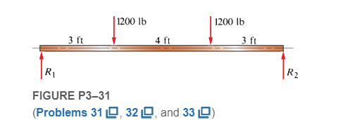
Chapter 3, Problem 31P
A beam is simply supported and carries the load shown in Figure P3−31. Specify suitable dimensions for the beam if it is steel and the stress is limited to 18 000 psi, for the following shapes:
- Square
- Rectangle with height three times the width
- Rectangle with height one-third the width
- Solid circular section
- American Standard beam section
- American Standard channel with the legs down
- Standard steel pipe
Expert Solution & Answer
Want to see the full answer?
Check out a sample textbook solution
Students have asked these similar questions
A beam carries loads as shown in Figure P1 below. Specify the suitable
dimensions of the beam if the stress is limited to 18 000 psi, for the following shapes: a)
Square; and b) Solid circular section; c) rectangular cross section with h = 3b; and d)
rectangular cross section with height one-third the width.
P1
A
0.4 m
800 N
B
0.8 m
400 N
C
600 N
D
E
0.3 m<0.3 m 0.4 m
200 N
F
Figure 1a shows a simply supported beam, AB of length L = 5.6 m, with a uniform distributed load of w = 4.5 kN/m. The shear force diagram is shown below the beam and the cross-section in Figure 1b. The cross section has a constant thickness t = 8.7 mm, the width of the flange is b = 217.5 mm and height of the web is d = 211.41 mm.
1. Determine the position of the neutral axis.
2. Determine the moment of inertia about the neutral axis
3. Determine the maximum shear stress acting on the cross-section
4) The C-clamp shown below has rectangular cross-section A-A that is 33 mm tall by 12 mm
wide and the material is class 50 gray cast iron. Determine maximum tensile stress and factor of
safety for clamping force F = 3.2 kN. Ignore stress concentration factors. See Section 4.9 in
Norton for help with curved beams.
MPa
N
O MAX
|F
F
60 mm
40 mm
12 mm
33 mm
33 mm
Section A-A
A
Chapter 3 Solutions
Machine Elements in Mechanical Design (6th Edition) (What's New in Trades & Technology)
Ch. 3 - A tensile member in a machine structure is...Ch. 3 - Compute the stress in a round bar having a...Ch. 3 - Compute the stress in a rectangular bar having...Ch. 3 - A link in a packaging machine mechanism has a...Ch. 3 - Two circular rods support the 3800 lb weight of a...Ch. 3 - A tensile load of 5.00 kN is applied to a square...Ch. 3 - An aluminum rod is made in the form of a hollow...Ch. 3 - Compute the stress in the middle portion of rod AC...Ch. 3 - Compute the forces in the two angled rods in...Ch. 3 - If the rods from Problem 9 are circular, determine...
Ch. 3 - Repeat Problems 9 and 10 if the angle is 15 .Ch. 3 - Figure P312 shows a small truss spanning between...Ch. 3 - The truss shown in Figure P313 spans a total space...Ch. 3 - Figure P314 shows a short leg for a machine that...Ch. 3 - Consider the short compression member shown in...Ch. 3 - Refer Figure P38 . Each of the pins at A, B, and C...Ch. 3 - Compute the shear stress in the pins connecting...Ch. 3 - Prob. 18PCh. 3 - Prob. 19PCh. 3 - Prob. 20PCh. 3 - Prob. 21PCh. 3 - Compute the torsional shear stress in a circular...Ch. 3 - If the shaft of Problem 22 is 850 mm long and is...Ch. 3 - Compute the torsional shear stress due to a torque...Ch. 3 - Compute the torsional shear stress in a solid...Ch. 3 - Compute the torsional shear stress in a hollow...Ch. 3 - Compute the angle of twist for the hollow shaft of...Ch. 3 - A square steel bar, 25 mm on a side and 650 mm...Ch. 3 - A 3.00 in-diameter steel bar has a flat milled on...Ch. 3 - A commercial steel supplier lists rectangular...Ch. 3 - A beam is simply supported and carries the load...Ch. 3 - For each beam of Problem 31, compute its weight if...Ch. 3 - For each beam of Problem 31, compute the maximum...Ch. 3 - For the beam loading of Figure P334, draw the...Ch. 3 - For the beam loading of Figure P334, design the...Ch. 3 - Figure P336 shows a beam made from 4 in schedule...Ch. 3 - Select an aluminum I-beam shape to carry the load...Ch. 3 - Figure P338 represents a wood joist for a...Ch. 3 - For Problems 39 through 50, draw the free-body...Ch. 3 - Prob. 40PCh. 3 - For Problems 39 through 50, draw the free-body...Ch. 3 - Prob. 42PCh. 3 - Prob. 43PCh. 3 - Prob. 44PCh. 3 - For Problems 39 through 50, draw the free-body...Ch. 3 - For Problems 39 through 50, draw the free-body...Ch. 3 - For Problems 39 through 50, draw the free-body...Ch. 3 - For Problems 4850, draw the free-body diagram of...Ch. 3 - For Problems 4850, draw the free-body diagram of...Ch. 3 - Prob. 50PCh. 3 - Compute the maximum tensile stress in the bracket...Ch. 3 - Compute the maximum tensile and compressive...Ch. 3 - For the lever shown in Figure P353 (a), compute...Ch. 3 - Compute the maximum tensile stress at sections A...Ch. 3 - Prob. 55PCh. 3 - Refer to Figure P38. Compute the maximum tensile...Ch. 3 - Prob. 57PCh. 3 - Refer to P342. Compute the maximum stress in the...Ch. 3 - Refer to P343. Compute the maximum stress in the...Ch. 3 - Prob. 60PCh. 3 - Figure P361 shows a valve stem from an engine...Ch. 3 - The conveyor fixture shown in Figure P362 carries...Ch. 3 - For the flat plate in tension in Figure P363,...Ch. 3 - For Problems 64 through 68, compute the maximum...Ch. 3 - For Problems 64 through 68, compute the maximum...Ch. 3 - For Problems 64 through 68, compute the maximum...Ch. 3 - For Problems 64 through 68, compute the maximum...Ch. 3 - Prob. 68PCh. 3 - Figure P369 shows a horizontal beam supported by a...Ch. 3 - Prob. 70PCh. 3 - Prob. 71PCh. 3 - The beam shown in Figure P372 is a stepped, flat...Ch. 3 - Figure P373 shows a stepped, flat bar having a...Ch. 3 - Figure P374 shows a bracket carrying opposing...Ch. 3 - Prob. 75PCh. 3 - Figure P376 shows a lever made from a rectangular...Ch. 3 - For the lever in P376, determine the maximum...Ch. 3 - Figure P378 shows a shaft that is loaded only in...Ch. 3 - Prob. 79PCh. 3 - Prob. 80PCh. 3 - A hanger is made from ASTM A36 structural steel...Ch. 3 - A coping saw frame shown in Figure P382 is made...Ch. 3 - Prob. 83PCh. 3 - Figure P384 shows a hand garden tool used to break...Ch. 3 - Figure P385 shows a basketball backboard and goal...Ch. 3 - Prob. 86P
Knowledge Booster


Learn more about
Need a deep-dive on the concept behind this application? Look no further. Learn more about this topic, mechanical-engineering and related others by exploring similar questions and additional content below.Similar questions
- -15 A composite beam is constructed froma wood beam (3 in. x 6 in.) and a steel plate (3 in, wide). The wood and the steel are securely fastened to act as a single beam. The beam is subjected to a positive bending moment M. = 75 kip-in. Calculate the required thickness of the steel plate based on the following limit states: Allowable compressive stress in the wood = 2 ksi Allowable tensile stress in the wood = 2 ksi Allowable tensile stress in the steel plate = 16 ksi Assume that Ew= 1,500 ksi and es= 30,000 ksi.arrow_forwardA large precast concrete panel for a warehouse is raised using two sets of cables at two lift lines, as shown in the figure part a. Cable 1 has a length L1 = 22 Ft, cable 2 has a length L2= 10 ft, and the distance along the panel between lift points Band D is d = 14 ft (see figure part b). The total weight of the panel is W = 85 kips. Assuming the cable lift Forces F at each lift line are about equal, use the simplified model of one half of the panel in figure part b to perform your analysis for the lift position shown. Find the required cross-sectional area AC of the cable if its breaking stress is 91 ksi and a factor of safety of 4 with respect to failure is desired.arrow_forwardA square wood platform is 8 ft × 8 ft in area and rests on masonry walls (see figure). The deck of the platform is constructed of 2-in. nominal thickness tongue-and-groove planks (actual thickness 1.5 in.; sec Appendix CL) supported on two S-ft long beams. The beams have 4 in. × (i in. nominal dimensions (actual dimensions 3.5 in. × 5.5 in.). The planks arc designed to support a uniformly distributed load n ( lb/ft" i acting over the entire top surface of the platform. I be allowable bending stress for the planks is 2400 psi and the allowable shear stress is 100 psi. W ben analyzing the planks, disregard their weights and assume that their reactions are uniformly distributed over the top surfaces of the supporting beams. (a) Determine the allowable platform load Mr. (lb/ft2) based upon the bending stress in the planks. (b) Determine the allowable platform load if-. (lb/ft-) based upon the shear stress in the planks. (c) Which of the preceding values becomes the allowable load alolow on the platform? Hints: Use care in constructing the loading diagram for the planks, noting especially that the reactions are distributed loads instead of concentrated loads. Also, note that the maximum shear forces occur at the inside faces of the supporting beams.arrow_forward
- A suspender on a suspension bridge consist of a cable that passes over the main cable (see figure) and supports the bridge deck, which is Far below. The suspender is held in position by a metal tie that is prevented from sliding downward by clamps around the suspender cable. Let P represent the load in each part of the suspender cable, and let represent the angle of the suspender cable just above the tie. represent the allowable tensile stress in the metal tie. (a) Obtain a formula for the minimum required cross-sectional area of the lie. (b) Calculate the minimum area if P = 130 kN, = 75°, and allow=80 .arrow_forwardA flat bar of width b and thickness t has a hole of diameter d drilled through it (see figure). The hole may have any diameter that will fit within the bar. What is the maximum permissible tensile load Pmaxif the allowable tensile stress in the material is st?arrow_forwardTwo wood beams, each of rectangular cross section (3.0 in. x 4.0 in., actual dimensions), are glued together to form a solid beam with dimensions 6.0 in. x 4.0 in. (sec figure). The beam is simply supported with a span of S ft. What is the maximum moment Mmaxthat may be applied at the left support if the allowable shear stress in the glued joint is 200 psi? (Include the effects of the beams own weight, assuming that the wood weighs 35 lb/ft3.) Repeat part (a) if Mmaxis based on allowable bending stress of 2500 psi.arrow_forward
- a) For the composite beam section in Figure Q6a, calculate the second moment of area about its centroidal x-x axis (Ixx centroid), where b₁ = 125.50 mm, b₂ = 25.75 mm, b3 = 36.35 mm, d₁ = 78.00 mm and d₂ = 24.00 mm Give your answer to 2 decimal places. b2 →→ dz Load b1 Support b3 → Figure Q6a b) Figure Q6b shows a simply supported 3.75 m long beam with a solid round cross- section and a concentrated point load of 250 kN acting at the mid-point of the beam. If the diameter of the beam cross-section is 165 mm, calculate the maximum tensile stress [Otensile_max] and the maximum compressive stress [Ocompressive_max] experienced by the beam. Use lxx = [¹/4] for the second moment of area of a round section beam about its x-x centroid axis. Assume that the weight of the beam is zero and that the beam section is solid and uniform along its entire length. Give your answer in N/mm² to 2 decimal places. d1arrow_forwardQuestion 1 The couple and evenly distributed load in Figure Q1 are both applied to a simply supported steel beam with a channel-type cross section. Determine the maximum compressive and tensile stresses in the beam. 20 kN/m 3 m 10 kN-m Đ 1m 1m. Figure Q1 40 mm 225 mm 40 mm 40 mm 200 mmarrow_forwardA flanged wooden shape is used to support the loads shown on the beam. The dimensions of the shape are shown in the second figure. Assume LAB = 7 ft. LBC= 2 ft, LCD= 4 ft,LDE = 3 ft, Pc= 1720 lb, Pe=2360 lb, WAB=850 lb/ft, b₂ = 8 in., b₂ = 2 in., b3 = 4 in., d₁ = 2 in., d₂ = 12 in., d3= 2 in. Consider the entire 16-ft length of the beam and determine: (a) the maximum tension bending stress or at any location along the beam, and (b) the maximum compression bending stress ocat any location along the beam. Answers: (a) OT (b) oc= i = i WAB LAB B Pc LBC b₁ b3 C LCD ·b₂ OD psi. psi. d₁ d3 LDE PE Earrow_forward
- Task 1 (a) A steel cantilever beam with a 1-in-diameter round cross section and length of 10 in is loaded at the tip with a transverse force of 1000 lbf and an axial force of 5000 lbf, as shown in the figure. Study the significance of the transverse shear stress in combination with tension and bending by calculating magnitudes of the stresses. Explain and comment on the stresses and strains generated. 1000 Ibf 1 in dia. Cross section at the wall 5000 Ibf (b) Consider a square element in the x-y plane with side length of 3 cm. The thickness of the element is 7 mm. The element has modulus of elasticity of 200 GPa and Poison's ratio of 0.33. If the element is subjected to forces in the x and y directions of 3 KN and 1.5 KN, respectively, find the dimensions of the loaded element. (c) Consider a cubic element with side length of 4 cm. The element has modulus of elasticity of 80 GPa and Poison's ratio of 0.3. If the element is subjected to equal forces in the x, y and z direction of 3 KN.…arrow_forward1. Question: With a pin on the AB beam A and a short lever BC as shown in the figure is supported. A, B and C pins have a diameter of 18 mm. P and a are given together Take as values given opposite your names in the table. This upload is above, below in your name on the pin (column 5 Calculate the shear stress occurring on only one of the specified pins A, B and C). P(kN)=30 a(0)=60 pin=A 4P 2P 0.5 m 4P 0.5m 1.5 m 1.5 m Barrow_forwardA flanged wooden shape is used to support the loads shown on the beam. The dimensions of the shape are shown in the second figure. Assume LAB = 7 ft, LBc= 2 ft, LcD = 3 ft, LDE = 4 ft, Pc= 1760 Ib, PE= 1620 lb, wAB = 830 lb/ft, b1 = 6 in., b2= 2 in., b3= 4 in., d1= 2 in., d2 = 7 in., d3= 2 in. Consider the entire 16-ft length of the beam and determine: (a) the maximum tension bending stress or at any location along the beam, and (b) the maximum compression bending stress oc at any location along the beam. Pc PE WAB B |C LAB LBC LCD LDE b1 di |dz - b2 dz bzarrow_forward
arrow_back_ios
SEE MORE QUESTIONS
arrow_forward_ios
Recommended textbooks for you
 Mechanics of Materials (MindTap Course List)Mechanical EngineeringISBN:9781337093347Author:Barry J. Goodno, James M. GerePublisher:Cengage Learning
Mechanics of Materials (MindTap Course List)
Mechanical Engineering
ISBN:9781337093347
Author:Barry J. Goodno, James M. Gere
Publisher:Cengage Learning
Understanding Failure Theories (Tresca, von Mises etc...); Author: The Efficient Engineer;https://www.youtube.com/watch?v=xkbQnBAOFEg;License: Standard youtube license